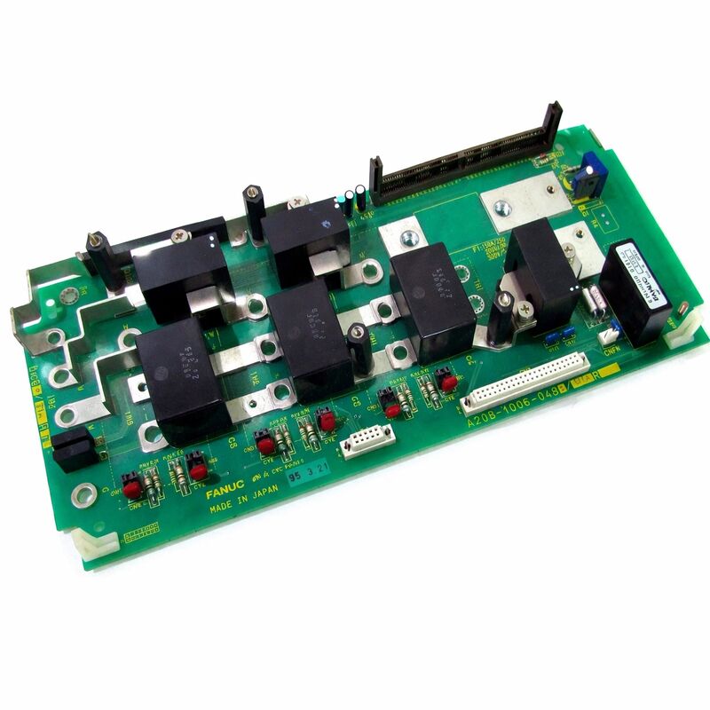
FANUC A20B-1006-0487 | Alpha Spindle Module Wiring PCB — SPM Series, Japan Origin
Part Number: A20B-1006-0487
Manufacturer: FANUC Corporation (Japan)
Product Type: Spindle Amplifier Module Wiring PCB
Board Series: A20B-1006
Application: FANUC Alpha SPM (Spindle Amplifier Module) series
Drive Family: FANUC Alpha series drives
Overview
The A20B-1006-0487 is the wiring PCB for FANUC's Alpha series SPM — Spindle Amplifier Module. In the FANUC Alpha drive architecture, the spindle amplifier module is the unit that powers the CNC machine tool's spindle motor, converting the DC bus voltage from the PSM into the variable-frequency AC that drives the spindle at its commanded speed and torque.
The A20B-1006-0487 is the internal wiring board within this module: the board that routes, connects, and interfaces the various signals and power paths between the module's other internal components.
A wiring PCB — also called a wiring board or interconnect board — is distinct from both the control PCB and the power PCB in the drive unit. The control PCB contains the processing electronics and servo algorithm execution.
The power PCB interfaces directly with the output transistors. The wiring PCB provides the physical routing infrastructure that connects these boards to the module's external connectors, internal sensors, power bus connections, and protection devices.
Without the wiring board, the module's internal components cannot communicate with each other or with the external drive system.
The A20B-1006 series covers wiring PCBs for FANUC's Alpha drive modules across a range of current ratings and configurations. The -0487 variant is matched to specific SPM models within this series.
It is manufactured in Japan to FANUC's production standards and is designed for the thermal and electrical environment inside an operating Alpha spindle drive.
Key Specifications
| Parameter |
Value |
| Part Number |
A20B-1006-0487 |
| Manufacturer |
FANUC Corporation |
| Product Type |
Wiring PCB (Interconnect Board) |
| Board Series |
A20B-1006 |
| Application |
FANUC Alpha SPM Spindle Amplifier Module |
| Drive Family |
FANUC Alpha series |
| Origin |
Japan |
| Operating Temperature |
0 – 55°C (as installed in drive module) |
| Storage Temperature |
−20 – 55°C |
| Humidity |
75% RH max (non-condensing) |
| Condition Available |
New (surplus) / Refurbished / Repaired |
The Alpha SPM — Spindle Drive in FANUC Architecture
The FANUC Alpha SPM is the spindle drive module in FANUC's shared DC bus drive system. It operates alongside the PSM (Power Supply Module) and the SVM (Servo Amplifier Modules) in a common cabinet. The PSM supplies the DC bus.
The SVM units power the servo axis motors. The SPM powers the spindle motor.
The spindle motor's control requirements are different from those of servo axis motors.
A spindle motor must run at commanded speeds from near-zero to the motor's maximum, maintain constant torque across a wide speed range, support torque control for threading operations, and orient precisely to a defined angular position for tool changes. The SPM handles all of these requirements.
Inside the SPM, several boards work together: the control PCB runs the speed and torque regulation algorithms, the output section drives the power transistors, and the wiring PCB — the A20B-1006-0487 — ties all the internal components together.
Every signal path from the control board to the power output stage, every sensor connection, every external connector interface, passes through the wiring PCB.
Function of the Wiring PCB
The term "wiring PCB" is specific and meaningful in the context of FANUC's drive module design. These boards serve as distribution centers within the module. They host the connectors that mate with the module's cable harness from the CNC.
They provide the internal connector positions that mate with the control board and the output transistor section.
They route the current measurement signals from the output stage's current transducers to the control board's measurement inputs.
Some wiring PCBs also host components that are functionally part of the circuit they support — snubber capacitors, gate resistors, current transducer conditioning circuits, and protection devices.
In these cases, the wiring board is not merely passive routing; it participates in the circuit function. The specific component population on the A20B-1006-0487 is determined by the SPM configuration it supports.
When the wiring PCB fails — from component damage, connector wear, trace damage, or contamination — the fault often appears as a complex multi-signal failure rather than a single clean fault.
Multiple alarms may appear simultaneously because the board provides the signal paths for many different monitored circuits.
This multi-alarm pattern can initially appear confusing until the common element — the wiring PCB — is identified.
Replacement in the Context of SPM Servicing
Alpha SPM units are typically serviced as modular assemblies. When a spindle drive module fails, the diagnosis determines whether the fault is in the control section (control board), the power section (output transistors), or the signal routing layer (wiring PCB). Replacing only the faulty board rather than the complete module is the economical and practical maintenance approach.
The wiring PCB is one of the three replaceable board layers in the Alpha SPM. Its replacement requires partial disassembly of the module housing to access the board's mounting position and internal connectors.
After replacement, the complete module function should be tested — spindle acceleration, constant speed under load, and orientation — before the machine is returned to production.
Ensure the replacement board's part number matches exactly. Wiring PCBs within the A20B-1006 series are configured for specific drive current ratings.
A board from a different current rating may appear similar but will have different component values or trace layouts that do not match the required circuit parameters.
FAQ
Q1: The Alpha spindle drive trips on an overcurrent alarm immediately at spindle enable, before any speed command is issued. Could the A20B-1006-0487 wiring PCB be at fault?
An overcurrent alarm before any speed command is consistent with either a wiring PCB fault or a control board fault. The overcurrent is being detected before the output transistors are switched — this points to a measurement circuit fault rather than actual excessive current.
Check the current measurement circuit's signal path on the wiring PCB: if the current transducers are connected to the wiring board and their signal conditioning is on the wiring board, a fault there produces a false overcurrent reading that triggers the alarm immediately.
Q2: The spindle runs at speed but orientation fails every time. The motor and encoder appear undamaged. Could the wiring PCB be involved?
Spindle orientation failure with normal speed operation points to the Z-signal (once-per-revolution position pulse) path. On some SPM wiring PCBs, the encoder feedback signal routing passes through the wiring board before reaching the control board.
A wiring PCB fault in the encoder signal path could interrupt or degrade the Z-signal while leaving the speed feedback (C-signal) intact.
Check the Z-signal at the wiring board's encoder connector output using an oscilloscope.
Q3: The SPM module was opened for inspection and the wiring PCB shows visible corrosion around one connector area. Should the board be replaced?
Visible corrosion around a connector indicates that moisture or corrosive contaminant has entered the module housing and reached the board.
Corrosion on connector contacts increases contact resistance and can produce intermittent or permanent signal faults.
A board with active visible corrosion should be replaced rather than cleaned — the corrosion typically extends into the connector contacts beyond what's visible on the surface, and cleaning rarely fully restores affected contacts to reliable function.
Q4: Can the wiring PCB be tested outside the drive module?
A meaningful functional test of a wiring PCB requires it to be connected to the surrounding circuits it routes — the control board, the output stage, and the external connections. Isolated testing of a passive wiring board is limited to continuity measurements and visual inspection of the traces and connections.
To confirm the board functions correctly, it must be tested within the complete module assembly under operating conditions.
Q5: After replacing the wiring PCB, should any spindle parameters be re-entered?
Spindle parameters are stored in the CNC controller's memory (FROM/SRAM), not in the SPM module's wiring PCB. Replacing the wiring board does not affect the parameter storage.
However, after any SPM service work, confirm that the spindle initialization sequence completes correctly and that the spindle speed calibration and orientation parameters are producing the expected machine behavior before releasing the machine to production.

 Your message must be between 20-3,000 characters!