FANUC A20B-1007-0880 | Alpha i SVM Interface Adapter PCB — A20B-1007 Series / Servo Drive Connection Board
Servo Drive Interface in the A20B-1007 Series
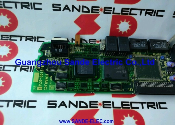
The A20B-1007-0880 is an interface adapter PCB that handles signal routing and connector interface between the Alpha i SVM (Servo Motor Module) drives and other elements of the FANUC CNC control system. In the FANUC drive system architecture, this type of board provides the physical and electrical bridging layer between the main CNC control unit and the servo amplifier connections — routing feedback signals, alarm outputs, and command inputs through a defined connector arrangement.
The A20B-1007 series covers a range of interface, connection, and operator panel PCBs that serve different positions in the FANUC CNC and robot system architecture. The -0880 variant is specifically associated with Alpha i SVM drive connections, distinguishing it from other A20B-1007 series boards that serve I/O, operator panel, or other interface roles.
When this board fails, the signals it routes between the Alpha i SVM drives and the control system are interrupted. The result is typically servo communication alarms or a failure of the affected axis or drive connection to initialise, while the CNC and other drive channels may continue to function.
Key Specifications
| Parameter |
Value |
| Part Number |
A20B-1007-0880 |
| Series |
A20B-1007 |
| Function |
Interface adapter — Alpha i SVM connector |
| Type |
Connection/interface PCB |
| Origin |
Japan |
Connector Condition and Failure Modes
Interface adapter boards fail through two main mechanisms. Physical connector damage — bent pins, corrosion on contact surfaces, or mechanical damage to connector housings from repeated mating cycles — can interrupt specific signal paths while leaving others intact. Electronic component failure on the board (protection ICs, buffer circuits) can disrupt signal integrity more broadly.
Before replacing the A20B-1007-0880, inspect all connectors attached to it. Fully reseat every harness connector and check for signs of corrosion or physical pin damage. A significant portion of interface board "failures" are resolved by cleaning and reseating connectors. If the fault persists with confirmed good connections, the board itself requires replacement.
FAQ
Q1: What does the A20B-1007-0880 do in the Alpha i SVM drive system?
It is the interface adapter PCB that routes signals between the Alpha i SVM servo amplifier connections and the CNC control system. It provides the physical connector interface and signal routing at a defined position in the drive cable chain. When it fails, the servo communication or feedback signals it routes are interrupted, producing axis alarms or failure to initialise.
Q2: How is a fault in this board identified before ordering a replacement?
Servo or communication alarms on the axis or axes connected through this board, combined with confirmed good motor cables and encoder cables, point to the interface board. Reseat all connectors attached to the board first — intermittent alarm conditions that clear on connector reseating confirm a connection issue rather than board failure. Persistent alarms with confirmed good connections confirm the board.
Q3: Does replacing the A20B-1007-0880 require CNC parameter changes?
No. Interface adapter boards do not store CNC parameters. Their function is signal routing only. After physical replacement and connection, verify normal CNC and drive communication before returning the machine to production.
Q4: Why is exact part number matching important for A20B-1007 series boards?
The A20B-1007 series contains boards serving different interface positions — operator panel PCBs, connection plates, and connector adapter boards each carry different signal routing arrangements. Visual similarity between adjacent variants does not mean functional compatibility. A wrong A20B-1007 variant in the Alpha i SVM connector position routes the wrong signals or produces an incomplete connection. Confirm A20B-1007-0880 specifically from the installed board's label.
Q5: What handling precautions apply to the A20B-1007-0880?
Standard ESD precautions: ground yourself before handling, handle by board edges, avoid contact with circuit traces and components. Store in anti-static packaging. If the board has been stored for an extended period, inspect connector contact surfaces for oxidation before installation — oxidised contacts on an otherwise functional board produce intermittent connection problems identical to board failure symptoms.

 Your message must be between 20-3,000 characters!