FANUC A20B-1007-0881 | I/O Module PCB — CNC, Robot and Industrial Automation Systems, Japan Origin
Part Number: A20B-1007-0881
Manufacturer: FANUC Corporation (Japan)
Product Type: I/O Module PCB (Input / Output Signal Interface Board)
Board Series: A20B-1007
Application: FANUC CNC, robot, and industrial automation systems
Function: Processing discrete input and output signals between the controller and machine field devices
Overview
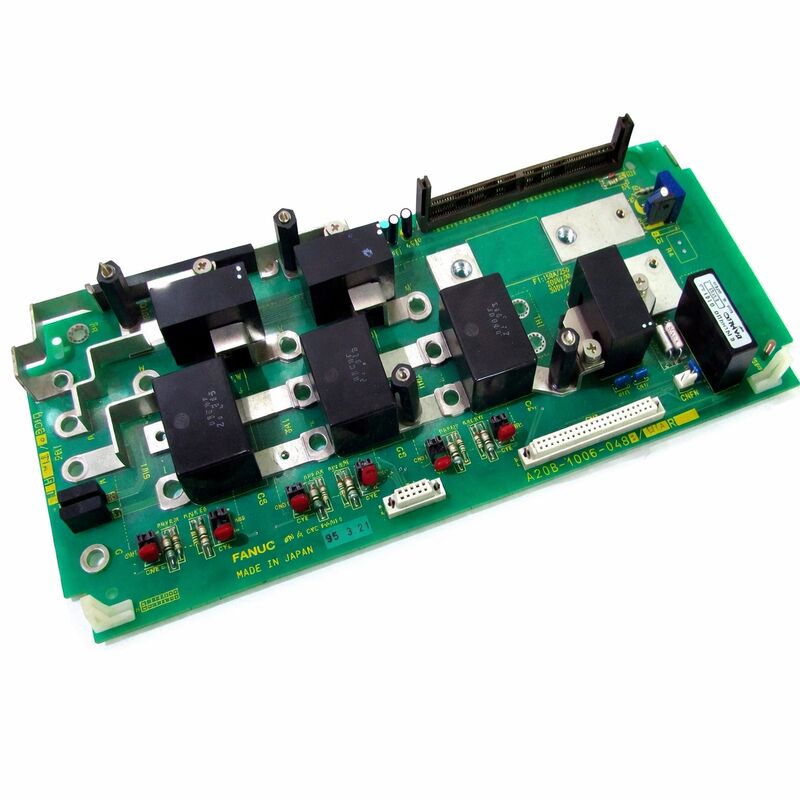
The A20B-1007-0881 is an input/output module printed circuit board from FANUC's A20B-1007 series — boards designed to interface the CNC controller or robot controller with the machine tool's or automation system's field-level devices.
The I/O module is where the gap between the controller's digital logic and the physical machine is bridged. Machine tool limit switches, solenoids, proximity sensors, door interlocks, coolant valves, tool change mechanisms, and operator panel buttons all connect to the machine through the I/O interface.
The controller reads machine states through the input side and commands machine actions through the output side.
The A20B-1007 series serves across FANUC's CNC and robot product range — the same I/O architecture that handles machine interface in a turning centre also appears in robot controller cabinets, handling the discrete signals that coordinate the robot's interactions with its workcell.
Limit switches that confirm the robot's gripper is open or closed, safety signals from light curtains, cycle start signals from part present sensors — all of these pass through the I/O module into the controller's PMC (Programmable Machine Controller) where the machine's automation logic processes them.
The A20B-1007-0881 processes input signals from the machine's field devices and output signals from the PMC to the machine's actuators.
It operates through FANUC's I/O Link — a serial communication bus that connects the controller's PMC to distributed I/O modules.
The I/O Link protocol packages input data from multiple I/O modules into a serial stream that the PMC reads on a defined cycle.
Output data from the PMC flows back through the same link, updating the module's outputs on each cycle.
Key Specifications
| Parameter |
Value |
| Part Number |
A20B-1007-0881 |
| Manufacturer |
FANUC Corporation |
| Product Type |
I/O Module PCB |
| Board Series |
A20B-1007 |
| Application |
FANUC CNC, robot and automation controllers |
| Function |
Discrete DI/DO signal processing via I/O Link |
| Signal Voltage (typical) |
24V DC |
| Communication |
FANUC I/O Link |
| Origin |
Japan |
| Operating Temperature |
0 – 55°C |
| Storage Temperature |
−20 – 60°C |
| Condition Available |
New (surplus) / Refurbished / Repaired |
I/O Link Architecture — How FANUC Distributes Field I/O
FANUC's I/O Link is a serial bus that allows the CNC or robot controller's PMC to communicate with I/O modules distributed across the machine or workcell. Rather than running individual signal wires from each machine I/O point back to the controller, the I/O Link carries all the I/O data in serial format on a small number of conductors.
I/O modules distributed along the I/O Link decode their portion of the serial stream, set their output signals accordingly, and read their input signals back into the stream.
The A20B-1007-0881 is one of many I/O module types that connect to the FANUC I/O Link. Each module occupies a defined number of I/O points on the bus.
The PMC's I/O mapping assigns specific PMC addresses to each module's I/O points.
The machine builder configures this mapping during machine commissioning — the PMC ladder program that runs the machine's automation logic reads from and writes to these PMC addresses to interact with the physical machine.
This architecture means that replacing a failed I/O module requires restoring the I/O point mapping if any module configuration data is stored on the module itself.
In most FANUC I/O Link implementations, the configuration is stored in the CNC's PMC parameters — the module is inherently addressed by its position on the bus, and no module-specific configuration needs to be reloaded after replacement.
Field Device Interfacing — Inputs and Outputs
The input side of the A20B-1007-0881 processes signals from field devices — contacts, sensors, and switches that report machine states to the controller. Input signals at the standard 24V DC level are optically isolated before reaching the module's logic circuitry.
Optical isolation prevents machine-side voltage transients, caused by solenoid switching or other inductive loads, from reaching the controller electronics.
The output side drives field device coils and signal loads. Output signals at 24V DC drive relay coils, solenoid valves, indicator lights, and other loads.
The output circuits have defined current capacity limits — exceeding these limits can damage the output circuit.
Correct output loading and fuse sizing are important aspects of the machine's electrical design.
Both input and output signal states are visible through the CNC's I/O diagnostic screen. The controller can display the current state of each I/O point in real time, which is the primary diagnostic tool for I/O-related machine faults.
An output that should be on but is off, or an input that reports a state inconsistent with the physical machine, points to either the I/O module or the field wiring.
Fault Diagnosis
I/O module failures fall into two broad categories: complete module failure and individual I/O point failure.
A complete failure prevents I/O Link communication from the module entirely — the CNC reports a communication alarm for the affected module address, and all I/O points associated with that module read as failed.
Individual point failures are subtler — some inputs report incorrect states, or some outputs do not switch, while the rest of the module operates normally.
Before replacing the A20B-1007-0881, verify the 24V DC supply to the module is correct and stable.
An under-voltage condition on the 24V supply causes erratic I/O behaviour that mimics module failure but resolves when the supply is corrected. Check the I/O Link cable connections — a loose or corroded connector produces communication errors.
FAQ
Q1: The CNC reports an I/O Link communication alarm for the slot where the A20B-1007-0881 is installed. No other I/O modules show alarms. Is the module the fault?
An isolated I/O Link communication alarm for one module slot indicates either the module itself has failed or its I/O Link cable connection is faulty.
First check the I/O Link cable connectors at both the module and the upstream device. Clean and reseat them.
If the alarm persists after connector verification, the module has likely failed and should be replaced.
Q2: Several specific output points on the A20B-1007-0881 have stopped functioning. The corresponding output commands from the PMC are confirmed correct. Is this a module fault?
Multiple dead output points with confirmed correct PMC output commands indicate an internal output driver fault within the module. Individual output circuits can fail — typically due to sustained overcurrent, inductive kickback from incorrectly protected loads, or age-related failure of the output transistors.
If the failed points are on the same physical connector or output group, the failure may be localised to that section of the module's output circuitry.
Module replacement is the appropriate response.
Q3: After replacing the A20B-1007-0881, some machine functions operate correctly but others do not respond as expected. What should be checked?
Unexpected behaviour after module replacement usually means the I/O point address mapping is correct but the PMC ladder program's expectations about specific points are not being met.
Verify that the replacement module occupies the same I/O Link address position as the original — if the modules are physically installed in the same slot and the I/O Link configuration has not changed, the addressing should be identical.
Also check that the input signal polarity (normally open vs normally closed logic) matches between the original and replacement module if the module type supports selectable input logic.
Q4: The 24V supply to the A20B-1007-0881 is intermittently fluctuating between 20V and 26V due to an upstream power supply issue. What damage risk does this create for the module?
Voltage excursions above 26V can exceed the rated voltage of the input and output protection circuits, potentially causing permanent damage to the module's optical isolators and output drivers.
Excursions below 20V may cause input signals to be misread (inputs may not reliably turn on at low supply voltage) and outputs to be unable to drive their load current.
Rectify the supply voltage problem before continuing operation — running with an unstable 24V supply will shorten the module's service life significantly.
Q5: The machine builder's documentation for this I/O module is unavailable. How can the I/O point count and addressing of the A20B-1007-0881 be determined?
The I/O point count and I/O Link addressing can be read from the CNC's I/O configuration screen. Most FANUC i-series and 0i-series controllers display the I/O module map showing each module's I/O Link address and the number of DI and DO points it provides.
The CNC's PMC I/O address allocation table shows which PMC addresses correspond to each module's points.
For the physical pin-to-point mapping, the module's label or the original machine builder's wiring documentation are the correct references.

 Your message must be between 20-3,000 characters!