FANUC A20B-1008-0210 | Interface Control PCB — A20B-1008 Series, FANUC CNC and Robot Systems, Japan Origin
Part Number: A20B-1008-0210
Manufacturer: FANUC Corporation (Japan)
Product Type: Interface / Control PCB
Board Series: A20B-1008
Application: FANUC CNC and robot controller interface and safety circuits
Overview
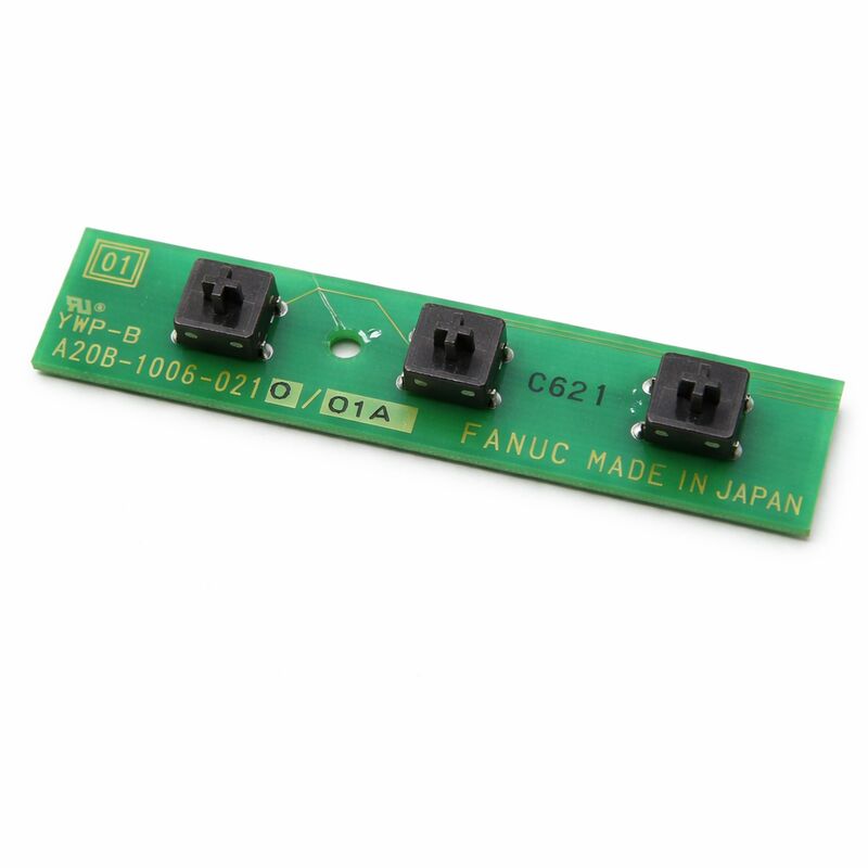
The A20B-1008-0210 is a printed circuit board from FANUC's A20B-1008 series. The A20B-1008 series is a collection of FANUC PCBs used in CNC and robot controller applications covering safety circuit processing, emergency stop input management, and controller interface functions.
These boards handle the signals that connect the machine's safety hardware — emergency stop buttons, fence interlocks, safety relay chains — to the CNC or robot controller's safety logic.
Safety circuit boards in FANUC systems occupy a unique position in the controller architecture.
They are not motion control boards or memory boards — their job is not to compute tool paths or store programs.
Their job is to monitor the machine's safety state continuously and to ensure that when a safety event occurs, the controller responds correctly and immediately.
A failure in the safety circuit board produces a machine that cannot enter automatic mode, or one that generates persistent safety alarms.
The A20B-1008 series PCBs support FANUC's CNC and industrial robot controller platforms.
These boards process the digital signals from the machine's safety sensors and relay chains, providing the input state information that the controller's safety logic reads.
They also drive safety-related output functions — engaging or releasing safety relays that control power to the drive system.
The A20B-1008-0210 performs these interface and safety circuit functions within this established series.
Key Specifications
| Parameter |
Value |
| Part Number |
A20B-1008-0210 |
| Manufacturer |
FANUC Corporation |
| Product Type |
Interface / Control PCB |
| Board Series |
A20B-1008 |
| Application |
FANUC CNC and robot controller safety and interface |
| Origin |
Japan |
| Operating Temperature |
0 – 55°C |
| Storage Temperature |
−20 – 60°C |
| Humidity |
75% RH max (non-condensing) |
| Condition Available |
New (surplus) / Refurbished / Repaired |
Safety Circuit Architecture in FANUC Systems
FANUC CNC and robot controllers implement safety through defined hardware circuits. The emergency stop chain is a series circuit: every E-stop button, every safety door interlock, every external safety device connects in series.
If any element of the chain opens — any button pressed, any door opened, any device triggered — the chain breaks and the emergency stop condition is signalled to the controller.
The safety circuit board monitors this chain.
It detects the chain state in real time and reports it to the controller's safety logic. When the chain breaks, the board signals the emergency stop condition.
The controller responds by releasing the servo ready signal, shutting down the drive enables, and bringing all motion to a stop.
This function is critical.
The board's response time to a safety event must be fast enough to stop the machine before a hazard can develop.
FANUC designs the safety circuit hardware for deterministic response — the signal path from input detection to servo shutdown is defined and tested, not subject to software scheduling delays.
When the A20B-1008-0210 fails, the controller may permanently report an emergency stop condition because it cannot see the safety chain state, or it may fail to detect a genuine emergency stop event because the input circuit is defective.
Either failure mode requires immediate board replacement.
Input Signal Processing
Safety circuit boards in the A20B-1008 series receive low-voltage digital input signals from the machine's safety hardware. These signals are typically 24V DC — the standard voltage for machine tool and robot safety circuits.
The board's input circuits condition these signals.
They filter out transient noise, debounce input switches to eliminate false triggering from contact bounce, and provide isolation between the external field wiring and the controller's internal logic circuits.
The isolation is important — the field wiring runs throughout the machine cabinet alongside motor cables and other noise sources.
Without isolation, noise coupled from the power wiring could produce false safety triggers or, worse, prevent genuine emergency stop events from being detected.
After conditioning, the processed input signals are presented to the controller's safety logic in a clean, reliable digital form that the logic can act on with confidence.
Handling and Replacement
Safety circuit board replacement requires careful attention to the connected wiring.
The safety chain wiring is specific — each connection point has a defined function, and incorrect reconnection after board replacement can leave a safety circuit path incomplete or misrouted.
Before removing the board, document every connector and its wiring.
Photograph the board in place from multiple angles if possible. Remove and reconnect each connector deliberately, confirming each cable returns to its correct position on the new board.
After installation, test the complete safety circuit before returning the machine to service. Verify that each emergency stop button individually stops the machine.
Verify that each safety door interlock individually triggers the emergency stop.
Verify that the E-stop can be released and the machine returned to normal operation through its normal reset sequence.
FAQ
Q1: The machine shows a permanent E-stop alarm even when all buttons are released and all doors are closed. The safety circuit wiring tests as continuous. Could the A20B-1008-0210 be at fault?
Yes. A permanent E-stop alarm with confirmed continuous safety chain wiring points to the safety circuit board.
The board is not correctly reading the chain state — either its input circuit has failed, or the board's power supply is not correct. Check the board's input power first.
If power is correct and the alarm persists with confirmed wiring, the board requires replacement.
Q2: The machine enters automatic mode correctly but the E-stop button sometimes fails to stop the machine immediately. What could cause this?
Intermittent E-stop response is a safety-critical fault that requires immediate investigation.
An intermittent response suggests the board's input circuit is degrading — contact resistance in the board's input connector, a failing optocoupler, or a high-resistance solder joint.
The machine must be taken out of service until this fault is resolved. Replace the board and test the E-stop function comprehensively before returning to production.
Q3: After a power surge in the facility, the machine shows safety alarms that did not previously exist. Is the A20B-1008-0210 likely damaged?
Power surges commonly damage input protection circuits on boards that connect to external wiring, because the external wiring acts as an antenna for surge energy.
Safety circuit boards are directly connected to field wiring and are exposed to this risk. Inspect the board for visible damage.
If the board's protection components have failed, the input circuits may be damaged even if the board appears intact.
Replace the board and confirm full safety circuit function.
Q4: Can this board be tested without installing it in the machine?
A meaningful functional test of a safety circuit board requires the board to be powered and connected to at least a simulated safety chain — resistor loads that simulate the chain closed state, and open-circuit tests that simulate E-stop events.
Testing on a bench with only power applied and no signal connections does not confirm the board's input circuit functionality.
If testing capability is limited, install the board in the machine and test its behavior in context with the full safety circuit wiring connected.
Q5: The safety circuit board's replacement resulted in correct safety operation, but after a few weeks the alarm returned. The board appears undamaged. What could cause a recurring fault?
A recurring safety fault after board replacement points to an environmental condition that is damaging or degrading the board.
The most common causes are vibration-induced connector contact issues (the connector works loose over time), coolant contamination entering the connector area, or intermittent power supply issues affecting the board. Inspect the board's connectors for any looseness or contamination.
Check the supply voltage to the board for any transient drops under heavy machine load.

 Your message must be between 20-3,000 characters!