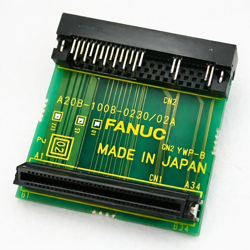
FANUC A20B-1008-0230 | Beta i Servo Amplifier Connector PCB — A20B-1008 Series, Japan Origin
Part Number: A20B-1008-0230
Manufacturer: FANUC Corporation (Japan)
Product Type: Connector PCB (Interface / Wiring Board)
Board Series: A20B-1008
Application: FANUC Beta i (βi) Series Servo Amplifier Drives
Overview
The A20B-1008-0230 is a connector printed circuit board from FANUC's A20B-1008 series — a family of interface and connector boards designed to provide the physical wiring and connector interface layer for FANUC drive products.
In the context of the Beta i (βi) series servo drives, the connector board is the component that brings together the drive's external connections: the FSSB optical fiber interface from the CNC, the servo motor power output terminals, the encoder feedback connector, the battery connection for absolute position retention, and the auxiliary signal connections for brake output and drive status.
The βi series represents FANUC's accessible-cost servo drive platform — designed for machine tools and automation applications where the full power density and peak performance of the Alpha series would be more than required.
A compact 50mm-wide single-axis module, the βi servo integrates its own power supply, removing the need for a separate PSM in smaller single-axis or dual-axis configurations. The drive communicates with the CNC via FSSB optical fiber — the same high-speed digital servo bus used across FANUC's i-series drive range — giving it the same precision closed-loop servo performance as its larger counterparts.
The connector board in a βi drive performs a specific and important function: it is the physical front panel of the drive module.
All the cables that connect the drive to the machine's wiring — the optical fiber from the CNC, the motor power cable, the encoder cable — terminate on this board.
The board routes these signals to the drive's internal circuit boards, and provides the LED status display and the battery holder that sit on the drive's front face.
When a connector board fails, it often fails in a way that affects one or more specific signal paths — an encoder connector that develops a poor contact, a battery connection that causes intermittent absolute position alarms, or an optical fiber interface that generates FSSB communication alarms.
Key Specifications
| Parameter |
Value |
| Part Number |
A20B-1008-0230 |
| Manufacturer |
FANUC Corporation |
| Product Type |
Connector PCB (Interface Board) |
| Board Series |
A20B-1008 |
| Application |
FANUC Beta i (βi) Series Servo Drives |
| Function |
Cable termination, signal routing, front-panel interface |
| Servo Interface |
FSSB (Fiber-optic Servo Serial Bus) |
| Encoder Interface |
Serial pulse coder feedback connection |
| Signal Voltage |
24V DC (auxiliary / brake circuits) |
| Origin |
Japan |
| Operating Temperature |
0 – 55°C |
| Status |
Available (check current stock) |
Beta i Drive Architecture — Connector Board Role
The βi servo amplifier is a compact integrated drive. Unlike the Alpha series SVM modules that separate control and power into distinct boards sharing a common DC bus, the βi unit is a self-contained module with its own internal power conversion.
Internally, the βi drive typically contains a main control PCB and the connector board.
The control PCB carries the servo control logic, the IGBT gate drive circuits, and the current sensing.
The connector board at the front of the module carries all the external connections and presents them to the technician who is wiring or servicing the drive.
This architecture means that connector board replacement is sometimes the specific solution for a βi drive fault.
If the servo amplifier generates alarms that correlate with specific connectors — encoder disconnection alarms when the encoder cable is known good, FSSB alarms when the optical cable is undamaged — the fault may be in the connector board's socket or signal path rather than in the main control circuitry.
Connector-level failures are a known aging mode: solder joint fatigue, connector socket wear from repeated cable insertions, and pin oxidation in industrial environments all manifest as intermittent or permanent connector faults.
FSSB and Encoder Interface
The FSSB optical fiber connection to the CNC is the primary control signal path for the βi drive.
The CNC's servo control software sends axis position commands to the drive through this link, and the drive reports encoder position and status back through the same fiber.
The A20B-1008-0230 houses the optical transmitter and receiver for this link.
A fault in these optical components — from fiber contamination, optical alignment shift, or component failure — causes FSSB communication alarms that prevent axis operation.
The encoder feedback connector on the same board receives the serial pulse coder signal cable from the servo motor.
This signal carries the motor's position, speed, and absolute position data back to the drive's control circuitry.
A poor connection at this point causes position errors, encoder disconnection alarms, or, in the case of absolute encoders, loss of reference position after a power cycle.
Absolute Encoder Battery Connection
The battery for absolute position encoder data retention is physically connected through the connector board. The battery — typically a 3V lithium cell — maintains the absolute position counter in the encoder during machine power-off periods.
The battery connection on the A20B-1008-0230 routes this 3V supply to the encoder through the encoder feedback cable.
When the battery depletes, the encoder loses its absolute position and the machine requires re-referencing after every power cycle.
Battery replacement on the βi drive must be performed while the drive's control power is on, to prevent position data loss during the battery exchange.
The A20B-1008-0230 provides the physical battery holder and connection circuit for this function.
FAQ
Q1: The βi servo drive is generating FSSB alarms but the optical fiber cable appears undamaged. Could the A20B-1008-0230 be the fault?
Yes. FSSB alarms with an undamaged cable point to either the optical transmitter/receiver on the drive's connector board or a contaminated fiber end.
First clean the optical fiber ends — even small contamination on the fiber face causes signal loss.
Use optical-grade cleaning tools. If the alarm persists after cleaning, try a spare fiber cable known to be good.
If the alarm still persists, the optical components on the A20B-1008-0230 are likely faulty.
Q2: The encoder disconnection alarm appears only intermittently. The encoder cable and encoder have been confirmed good. Is this a connector board fault?
Intermittent encoder alarms with confirmed good cable and encoder are consistent with a connector socket fault on the A20B-1008-0230. The encoder connector socket may have a pin with reduced contact force or a cracked solder joint that opens under thermal expansion.
Try reseating the encoder connector — clean the connector contacts and reseat firmly.
If the alarm returns after reseating, the socket on the connector board requires replacement or the board should be exchanged.
Q3: An absolute position alarm appears at every power-on, requiring the machine to re-reference all axes. The battery has been replaced. Does the fault now point to the A20B-1008-0230?
If the alarm persists after a confirmed battery replacement (performed with control power on to preserve data), the fault is either in the battery connection circuit on the A20B-1008-0230 or in the encoder itself.
Measure the battery voltage at the drive's battery connector — it should read the battery's nominal voltage (typically around 3V).
If the voltage is correct at the battery but the encoder still loses position, the encoder's internal backup has failed.
If the voltage is correct but drops to zero at the encoder connector, the connection path through the A20B-1008-0230 is interrupted.
Q4: The brake output on the βi drive is not releasing the motor brake correctly. The brake wiring has been checked. Is the connector board a suspect?
The brake control circuit — which releases the motor's holding brake during powered operation — routes through the connector board. A fault in the brake output connection on the A20B-1008-0230 can prevent the brake release signal from reaching the brake solenoid.
Confirm the brake output voltage at the drive's brake connector terminals.
If the drive software is commanding brake release but the correct voltage is absent at the terminals, the connector board's brake output circuit is faulty.
Q5: The A20B-1008-0230 is being replaced. Are there any settings or configurations on this board that need to be transferred from the original?
The A20B-1008-0230 connector board typically carries no configuration jumpers or switches specific to the axis configuration — these settings are on the drive's main control PCB. However, confirm this against the specific βi drive model's documentation before replacement.
The battery must be transferred from the original board or a fresh battery installed if the motor uses an absolute encoder.
Transfer the battery with control power on to avoid absolute position data loss.

 Your message must be between 20-3,000 characters!