FANUC A20B-1009-0300 | Connection PCB — A20B-1009 Series, FANUC CNC and Robot Systems, Japan Origin
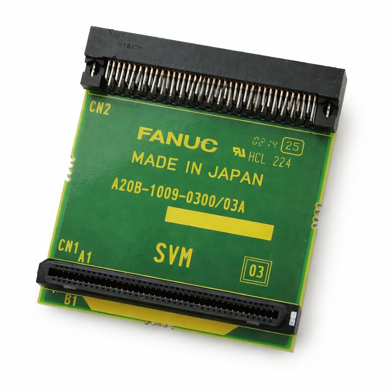
Part Number: A20B-1009-0300
Manufacturer: FANUC Corporation (Japan)
Product Type: Connection PCB
Board Series: A20B-1009
Application: FANUC CNC and robot controller internal interface
Overview
The A20B-1009-0300 is a connection printed circuit board from FANUC's A20B-1009 series. Connection boards in FANUC systems perform the physical and electrical interface function between different sections of a controller or between the controller and field wiring.
They route signals, match connector types, convert signal levels, or provide the physical mounting points and termination for cables that come from outside the controller cabinet.
The A20B-1009 series is a group of FANUC interface and connection PCBs used across CNC and robot controller applications.
These boards typically do not perform active signal processing — they are not CPUs or memory cards.
Instead they serve the essential role of translating the internal connector arrangement of the control unit into the physical connectors and signal paths that the machine or robot's external wiring requires.
The quality of this interface — the integrity of every connector and trace — directly affects the reliability of the system's communication with its surrounding machine hardware.
FANUC manufactures connection boards in Japan to the same quality standards as its processing boards.
Although these boards are often overlooked compared to CPU and memory boards, a failed connection board produces the same effect as a broken cable: signals fail to reach their destination, the CNC or robot misses sensor inputs or cannot drive its outputs, and faults appear.
Key Specifications
| Parameter |
Value |
| Part Number |
A20B-1009-0300 |
| Manufacturer |
FANUC Corporation |
| Product Type |
Connection PCB |
| Board Series |
A20B-1009 |
| Application |
FANUC CNC and robot controller interface |
| Origin |
Japan |
| Operating Temperature |
0 – 55°C |
| Storage Temperature |
−20 – 60°C |
| Humidity |
75% RH max (non-condensing) |
| Condition Available |
New (surplus) / Refurbished / Repaired |
The Role of Connection Boards in FANUC Systems
CNC and robot controllers are not monolithic devices. They contain multiple boards, each specialising in a specific control function, all communicating through a defined set of internal buses and connectors.
The signals that travel between these boards must eventually reach the outside world — the servo drives, the I/O field devices, the operator panels, and the communication networks.
Connection boards handle this transition.
An internal board may use a high-density connector that fits efficiently within the controller rack but is impractical for field wiring.
The connection board provides an adapter — converting from the internal connector arrangement to the cable and connector types that are appropriate for installation in the machine cabinet.
In FANUC robot controllers, the A20B-1009 series includes boards used for brake and gravity compensation unit connections, I/O connector conversion, and other internal interface functions.
Each variant in the series — identified by the trailing digits of the part number — serves a specific connection purpose defined by its placement within the controller architecture.
Why Connection Board Failures Occur
Connection boards fail for fewer reasons than active processing boards. They contain no processors to fail, no capacitors to age, no firmware to corrupt.
Their failure modes are primarily physical: mechanical damage to the PCB or its connectors from repeated mating cycles, corrosion from environmental contamination, damage from over-insertion force, or board flex from thermal cycling that breaks solder joints over time.
When a connection board fails, the symptoms mirror those of a cable fault. Signals that the controller expects to receive are absent.
Outputs that the controller drives do not reach the machine. Alarms appear that look like field device failures but are actually connection board faults.
Cable and connector checks that find nothing wrong should redirect attention to the connection board itself.
High-vibration environments accelerate connection board degradation.
The repeated micro-movements of vibration gradually work solder joints and connector contacts loose.
Regular inspection of connection boards in machines with high spindle speeds or significant cutting vibration is a sound preventive maintenance practice.
Handling and Replacement
Replacing a connection board is typically straightforward. Power down the system, document the cable connections before removal, disconnect all cables and the board mounting, fit the replacement board, and reconnect the cables in the documented order.
The documentation step is critical.
Connection boards can have multiple similar-looking connectors, and swapping two cables produces incorrect signal routing that can cause unexpected and hard-to-diagnose faults. Photograph or diagram the cable arrangement before beginning the removal.
After replacement, confirm all expected signals are present on the connection board's outputs before running the machine.
Use the controller's diagnostic I/O screens to verify that field inputs are reading correctly and that output commands are reaching the field devices.
FAQ
Q1: Several I/O signals stopped working simultaneously. The cables appear intact. Could the A20B-1009-0300 be at fault?
Multiple I/O failures with intact cables is a classic pattern for a connection board fault.
A failure of the connection board's internal bus — a cracked trace or failed solder joint — can take out a group of signals simultaneously rather than one at a time.
Check the connection board's connectors for any signs of damage or corrosion before concluding the board has failed.
Clean the connector contacts, reseat all connectors, and retest before ordering a replacement.
Q2: The connection board shows visible burn marks near one connector. Can it be repaired?
Burn marks indicate a previous overload event — excessive current through the connector or a nearby circuit.
Even if the cause of the overload is resolved, the board's PCB traces and nearby components may be degraded in ways not visible from the surface.
A board with burn damage is not reliable. Replace it rather than attempting to repair cosmetic damage over potentially compromised copper traces.
Q3: Is this board affected by SRAM battery backup requirements?
No. Connection boards are passive — they contain no memory, no processors, and no battery-backed storage.
There is no data to lose when the board is replaced. Unlike a CPU or memory board replacement, a connection board swap does not require data restoration from backup.
The machine's control data remains in the controller's memory boards, unaffected by the connection board replacement.
Q4: How do I confirm this is the correct connection board for my application?
Read the part number from the installed board's label. Match it exactly — including the A20B-1009-0300 suffix.
Within the A20B-1009 series, different variants serve different physical connector arrangements and signal assignments.
An incorrect variant installs mechanically but routes signals incorrectly. The installed board's label is the definitive identifier.
Q5: The connector pins on the installed board are bent. Should the board be replaced or the pins straightened?
Bent pins on a PCB connector should be carefully straightened if no permanent deformation exists at the base of the pin. Use appropriate small tools and work with care.
If any pin is broken at its base or if the PCB pad it solders to is lifted, replacement is necessary — a broken pin cannot be reliably repaired to the quality standard required for industrial control board use. Inspect under magnification before deciding.

 Your message must be between 20-3,000 characters!