FANUC A20B-2000-0170 | Zero-C Control Master PCB — 32-Bit, Series 0MC / 0TC / 0MD / 0TD, Discontinued
Part Number: A20B-2000-0170
Manufacturer: FANUC Corporation (Japan)
Product Type: Master Control PCB (Motherboard)
Architecture: 32-bit, Split architecture
Compatible Systems: FANUC Series 0MC, 0TC, 0MD, 0TD (Zero-C)
Configurations Supported: 0-T, 0-M, 0-W, 0-P, 0-G
Production Status: Discontinued; successor A20B-2000-0175
Weight: 5.36 lbs (approx. 2.43 kg)
Overview
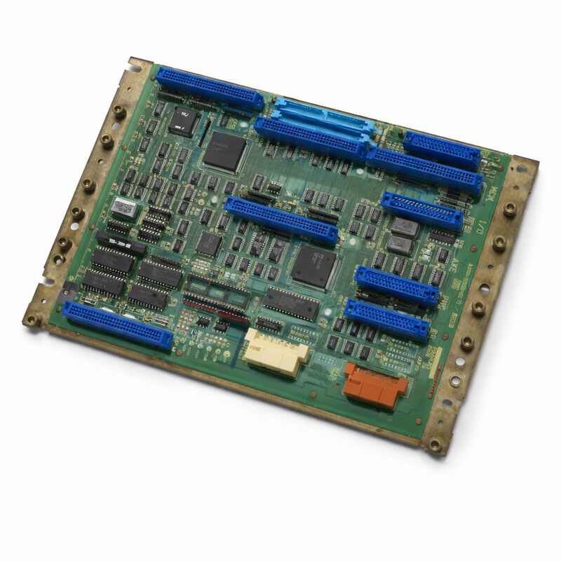
The A20B-2000-0170 is the master control PCB — the motherboard — for the FANUC Series Zero-C CNC controller. It is the central board that the entire Zero-C controller is built around. In FANUC's own terminology, this is the main 32-bit PCB that defines the Zero-C platform's generation and capability.
The Zero-C was one of FANUC's most successful and widely deployed CNC controller generations.
It found its way into turning centres (0TC, 0TD), machining centres (0MC, 0MD), and a range of other machine types across the global machine tool industry during its production era.
The result is an enormous installed base of Zero-C machines that continue to operate in production facilities worldwide. When the master board of one of these controllers fails, the A20B-2000-0170 is the replacement that restores it.
The board is half-size — smaller than the earlier 0-B generation main boards.
It acts as a backplane for the Zero-C's plug-in peripheral cards. The minimum configuration requires three peripheral boards: a memory card, an axis card, and an I/O card. Larger configurations add a graphics processor, a PMC-M card, additional axis boards for 5th and 6th axes, and a PC cassette for DNC communication.
This extensibility — fitting the same master board to many different machine configurations — made the Zero-C a highly configurable platform for machine builders.
This board has been discontinued by FANUC. The successor is the A20B-2000-0175.
When sourcing, confirm compatibility with the installed peripheral cards and system software before ordering.
Key Specifications
| Parameter |
Value |
| Part Number |
A20B-2000-0170 |
| Manufacturer |
FANUC Corporation |
| Product Type |
Master Control PCB (Motherboard) |
| Controller Series |
FANUC Series Zero-C (0C) |
| Compatible Systems |
0MC, 0TC, 0MD, 0TD |
| Configurations |
0-T, 0-M, 0-W, 0-P, 0-G |
| Architecture |
32-bit, split (distributed) processing |
| Board Size |
Half-size (smaller than predecessor 0-B board) |
| Successor Part |
A20B-2000-0175 |
| Weight |
5.36 lbs (approx. 2.43 kg) |
| Production Status |
Discontinued by Manufacturer |
| Origin |
Japan |
| Operating Temperature |
0 – 55°C |
| Condition Available |
New (surplus) / Refurbished / Repaired |
Split Architecture — Distributed Processing
The defining design characteristic of the A20B-2000-0170 is its split architecture. Unlike earlier FANUC CNC main boards that concentrated most processing on a single large board, the Zero-C master board distributes processing across its peripheral boards through a shared backplane.
The master board handles the core CNC functions — the NC program interpreter, the interpolation calculations, and the coordinate management. The axis board handles the servo command generation and feedback processing for its assigned axes.
The memory board handles program storage and retrieval. The PMC-M card (when fitted) handles the machine ladder logic independently.
This distribution of processing produced several practical benefits. Each board could be optimised for its specific function.
A failing axis board did not take down the full NC function. And the modular architecture allowed the same master board to serve configurations from simple 2-axis turning to complex 5-axis machining — just by changing the mix of peripheral boards plugged into the backplane.
Zero-C — The Swiss Army Knife of FANUC Controls
The Zero-C's configurability was remarkable for its era. The same A20B-2000-0170 master board could serve a simple gang tool lathe with 2 axes and a serial spindle, or a complex turn-mill centre with 5 axes, a C-axis, live tooling, and tailstock control.
The peripheral board selection, parameter configuration, and system software version determined the capability of any given installation.
This configurability meant the Zero-C appeared on machines from hundreds of different machine builders across every machining discipline.
The 0-T configuration served lathes. The 0-M configuration served machining centres.
The 0-W configuration served wire EDM machines. The 0-P configuration served punch presses. The 0-G configuration served grinding machines.
All ran from the same master board platform.
The practical consequence for maintenance is that replacement A20B-2000-0170 boards are transferable between machines of the same control generation, provided the peripheral boards and system software are correctly matched.
A board from a decommissioned 0MC can be a valid replacement in a running 0TC if the hardware and software compatibility is confirmed.
Replacing the Master Board — What to Expect
The master board holds no machine-specific data by itself — it is a processor board. Machine-specific data (parameters, programs, PMC ladder, tool offsets) is stored in the memory board's SRAM and FROM.
When replacing the A20B-2000-0170, these data are preserved in the memory board, which typically remains installed.
However, a complete pre-maintenance data backup to a memory card or external device is always the correct practice.
If the SRAM battery has been marginal and discharges during the board swap, the SRAM content can be lost even if the memory board remains installed.
A known-good backup makes that loss a recoverable event rather than a crisis.
After replacement, the controller should complete its normal startup sequence and load the previously stored programs and parameters from the memory board without issue — provided the replacement board is compatible with the installed peripheral boards and system software version.
FAQ
Q1: The Zero-C controller shows a RAM parity alarm on startup. Other boards appear normal. Is the master board the fault?
RAM parity alarms in the Zero-C system point to a memory fault, but the memory may be on the memory board rather than the master board.
Check which memory address the alarm references — the controller's diagnostic output will indicate whether the fault is in the common RAM, the NC RAM, or the PMC RAM.
If the fault references the master board's own RAM, the master board is suspect.
If it references the memory board's RAM, the memory board should be investigated first.
Q2: The machine has a 0TC configuration. Can the A20B-2000-0170 from a 0MC machine replace it?
Yes, the master board hardware is common across 0TC and 0MC configurations.
The differences between turning and machining centre configurations are determined by the axis board, the system software, and the parameters — not the master board itself.
A master board from a 0MC can serve a 0TC installation, provided the peripheral boards are confirmed compatible and the system software is loaded correctly.
Always back up the installed system before attempting the swap.
Q3: The A20B-2000-0170 is powered on but the display shows a white screen with no controller startup text. What is happening?
A white screen on startup typically indicates the graphics subsystem has received a signal but the NC processor has not yet started or has stopped early in the boot sequence. Check for any visible LED alarm patterns on the master board — these provide initial diagnostic information.
Common causes include failed memory board, corrupted FROM content, or a fault in the master board's own processor circuitry.
Inspect the peripheral board connections and confirm the memory board is properly seated.
Q4: Can the successor board A20B-2000-0175 replace the A20B-2000-0170 directly?
The -0175 is the designated successor to the -0170, but direct interchangeability should be confirmed for the specific installation.
Successor boards in FANUC's Zero-C series typically address hardware revisions while maintaining functional compatibility, but the system software version and peripheral board configuration should be verified against the -0175's compatibility range before installation.
Contact the machine tool builder or a qualified FANUC service organisation for confirmation specific to your configuration.
Q5: The Zero-C machine is displaying a servo alarm after the master board was replaced with a tested spare. The axis boards were not changed. What could cause this?
A servo alarm appearing only after a master board replacement points to a communication issue between the new master board and the existing axis boards.
Check that the master board is fully seated in the backplane and that all inter-board connectors are engaged.
Also verify that the system parameters — specifically the servo interface parameters — are intact in the memory board.
If parameters were lost during the swap, restoring from backup and re-entering the servo parameters should resolve the alarm.

 Your message must be between 20-3,000 characters!