FANUC A20B-2000-0175 | Zero-C Control Master PCB — 32-Bit 486, Series 0MC / 0TC / 0MD / 0TD
Part Number: A20B-2000-0175
Manufacturer: FANUC Corporation (Japan)
Product Type: Master Control PCB (Motherboard)
Processor: 32-bit Intel 486
Architecture: Split (distributed) architecture
Compatible Systems: FANUC FS0-C, FS0-D, FS-0MD, FS-0TD (Zero-C / Zero-D)
Configurations Supported: 0-T, 0-M, 0-W, 0-P, 0-G
Predecessor: A20B-2000-0170
Overview
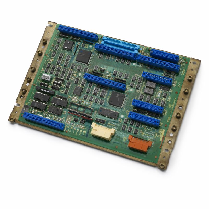
The A20B-2000-0175 is the 32-bit master control PCB for FANUC's Series Zero-C and Zero-D CNC systems. It is the successor to the A20B-2000-0170, sharing the same foundational architecture but incorporating a faster Intel 486 processor in place of the earlier board's processor.
The upgrade in processing speed improved the CNC's cycle time performance and responsiveness without requiring changes to the controller's peripheral board configuration.
Like its predecessor, the A20B-2000-0175 is a half-size board that acts as the backplane and central processor for the entire Zero-C controller.
All the peripheral boards — the memory card, the axis control board, the I/O board, and optionally the graphics processor and PMC-M card — plug into this master board or connect through it. The master board coordinates all of these, managing the CNC interpolation, program execution, and the communication between each subsystem.
The Zero-C platform, built around this board, was one of FANUC's most widely deployed controller generations.
Its extraordinary configurability — covering turning, milling, EDM, grinding, punch press, and other machine types from the same hardware platform — made it the choice for a huge range of machine tool builders.
Machines running this controller remain in production globally. The A20B-2000-0175 is the part that keeps them running when the master board fails.
Key Specifications
| Parameter |
Value |
| Part Number |
A20B-2000-0175 |
| Manufacturer |
FANUC Corporation |
| Product Type |
Master Control PCB (Motherboard) |
| Processor |
32-bit Intel 486 |
| Board Format |
Half-size, surface-mount |
| Architecture |
Split (distributed) across peripheral boards |
| Compatible Systems |
FS0-C, FS0-D, FS-0MC, FS-0TC, FS-0MD, FS-0TD |
| Configurations |
0-T, 0-M, 0-W, 0-P, 0-G |
| Predecessor |
A20B-2000-0170 |
| Axis Control |
2 to 4 axes (dependent on axis board fitted) |
| Origin |
Japan |
| Operating Temperature |
0 – 55°C |
| Storage Temperature |
−20 – 60°C |
| Condition Available |
New (surplus) / Refurbished / Repaired |
The 486 Processor Upgrade — What It Changed
The key hardware difference between the A20B-2000-0175 and its predecessor is the processor. The -0175 uses an Intel 486 processor, which provided a measurable improvement in processing throughput compared to the earlier board's CPU.
In CNC terms, this processing improvement manifested as faster interpolation — shorter cycle times for the same motion programs.
On machines running complex contouring programs with many short-segment moves, the additional processing headroom allowed the controller to look ahead further and interpolate more smoothly.
The 486 also handled the communication with peripheral boards more quickly, reducing latency in the overall control loop.
This improvement was significant without being disruptive. The peripheral board ecosystem — memory boards, axis boards, I/O boards — remained compatible.
A controller running the -0170 could be upgraded to the -0175 by swapping the master board and transferring the SMD modules, provided the peripheral boards were compatible with the faster processor's timing.
Split Architecture — The Zero-C Design Philosophy
The Zero-C master board is the centre of a split processing architecture. The master board itself handles the NC kernel — interpolation calculations, program parsing, coordinate management. The axis board fitted to the master board runs the digital servo interface, converting the NC's calculated positions into the pulse-width commands that drive the servo amplifiers.
The memory board holds the system programs, parameters, and NC programs.
The I/O board connects the machine's field wiring — sensors, solenoids, switches.
This separation of function was deliberate. Each board handled its specific task without competing with others for processing time.
The system was also maintainable: a failed axis board didn't take out the NC, and a failed memory board could be replaced without disturbing the master board.
The minimum configuration for a functional Zero-C system is three boards: master board, memory board, axis board, and an I/O board — typically the machine also includes a PC cassette for DNC communication.
Larger configurations add a graphics processor sub-system for enhanced display, a PMC-M board for more complex ladder programs, and additional axis boards for 5th or 6th axes.
Backward Compatibility with the -0170
The A20B-2000-0175 is the designated replacement for the A20B-2000-0170. In most configurations, the -0175 accepts the same peripheral boards and the same SMD modules (if any) as the -0170. When replacing an -0170 with an -0175, the peripheral boards remain in place and the SMD modules are transferred if applicable.
The key compatibility requirement to verify before substitution is the system software version.
The -0175 uses a later hardware revision. The system software on the memory board must be compatible with the -0175 board revision.
In most cases this is not an issue, but controllers running very early Zero-C system software versions may require a system software update when transitioning to the -0175.
FAQ
Q1: The Zero-C machine boots but the cycle time seems slower than expected. Could the master board be operating below its intended performance?
Slow cycle time on a Zero-C system can come from incorrect look-ahead parameters, a degraded clock circuit on the master board, or excessive interrupt load from a peripheral board. Check the controller's diagnostic screens for any processor busy indicators.
If the board's clock oscillator is degraded, it can run below its rated frequency — this produces consistent, reproducible slowdown rather than intermittent faults.
A board replacement is the only reliable remedy for a failed clock circuit.
Q2: After replacing the -0170 with an -0175, the machine starts but the axis board is not recognized. What could cause this?
Axis board recognition failure after a master board swap usually indicates a timing or hardware revision incompatibility between the -0175 and the axis board. Confirm the axis board revision is within the compatibility range for the -0175.
Check the backplane connections between the master board and the axis board. Also verify that any configuration switches on the axis board are set correctly for the system's axis count.
Q3: The Zero-C machine powers on, but the display stays blank after the initial startup flash. Other boards appear normal. Is the master board at fault?
A blank display after initial startup typically means the NC processor has not completed its boot sequence.
This could be the master board itself, or the memory board that the master board is trying to load software from.
Observe the diagnostic LEDs on the master board for the boot sequence status. A board that stops partway through with a specific LED pattern points to a defined fault location in the FANUC diagnostic chart.
A board that produces no LED activity at all suggests a processor or power fault on the master board.
Q4: Is the A20B-2000-0175 interchangeable between a 0MC and a 0TD machine?
The master board hardware is the same for all Zero-C variants. What differs between machine types is the system software, the axis board, and the parameters — not the master board.
A board from a 0MC can serve a 0TD and vice versa, provided the peripheral boards, system software, and parameters are appropriate for the target machine.
Always restore the target machine's data backup after any master board replacement.
Q5: The -0175 board was purchased as a tested spare. How should it be stored to maintain its condition?
Store in original or replacement anti-static packaging at stable room temperature. Keep away from humidity, direct sunlight, and temperature extremes.
Label the bag with the part number and the test date. Every few years, inspect the board contacts for any oxidation.
If the board carries an SRAM backup battery, check and replace the battery before the board is needed in service — a battery failure during storage does not affect the board itself, but means SRAM data won't survive if the board is ever powered with data in SRAM.

 Your message must be between 20-3,000 characters!