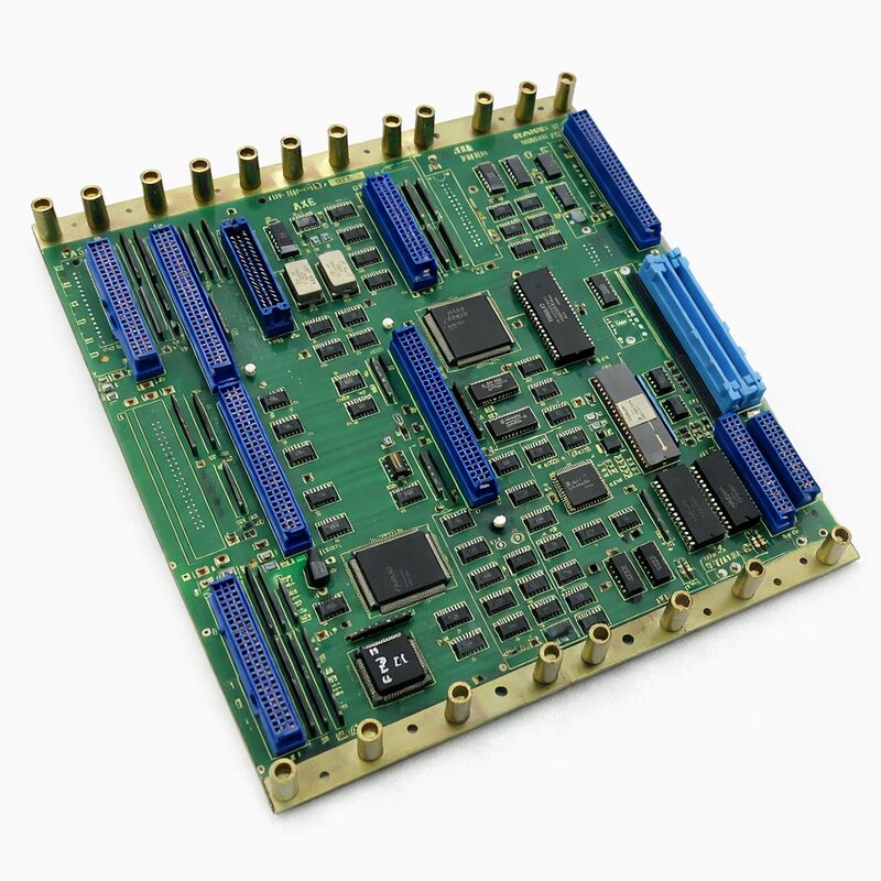
FANUC A20B-2001-0120 | Series 0-D Half-Size Master PCB — 0-MD / 0-TD CNC Controller, Japan Origin
Part Number: A20B-2001-0120
Manufacturer: FANUC Corporation (Japan)
Product Type: Master PCB (Motherboard / Backplane)
Board Series: A20B-2001
Generation: Series 0 Model D (mid-generation, half-size)
Compatible Systems: Series 0-D — 0-MD, 0-TD CNC controllers
Architecture: Distributed — peripheral boards plug into master board
Peripheral Boards: Memory, axis, I/O, PMC (cassette or board)
Overview
The A20B-2001-0120 is the master PCB for FANUC's Series 0 Model D CNC controllers — the half-size format motherboard that sits at the centre of the 0-D controller architecture. It occupies a specific position in the chronology of the FANUC 0 series: a mid-generation board that sits between the earlier full-size 0-C variants and the later revised half-size designs that followed it.
The 0-D generation refined the 0-C architecture with updates to the processing speed, serial drive interface support, and system capability while maintaining the same fundamental distributed board architecture that made the 0-series so adaptable.
The master board's role is architectural, not just computational. It is the physical and electrical backplane that all other boards in the controller plug into. Memory boards, axis control boards, I/O boards, and PMC boards all connect to the A20B-2001-0120 and communicate through it.
The master board coordinates the bus that these peripheral boards share. It also carries the main processor that runs the CNC operating software and interprets the G-code and M-code programs that drive the machine.
FANUC's 0-D found its way into an enormous number of machine tools — turning centres in the 0-TD configuration, machining centres in the 0-MD configuration, and various 0-WD, 0-PD variants for wire EDM and punch press applications. Many of these machines remain in productive use today.
The A20B-2001-0120 is the component that keeps them running.
Key Specifications
| Parameter |
Value |
| Part Number |
A20B-2001-0120 |
| Manufacturer |
FANUC Corporation |
| Product Type |
Master PCB (Backplane/Motherboard) |
| Board Series |
A20B-2001 |
| Series |
FANUC Series 0 Model D |
| Format |
Half-size |
| Configuration |
0-MD (machining centre), 0-TD (turning centre) |
| Architecture |
Distributed (peripheral boards plug in) |
| Peripheral Board Slots |
Memory, Axis, I/O, PMC |
| Origin |
Japan |
| Operating Temperature |
0 – 55°C |
| Storage Temperature |
−20 – 60°C |
| Condition Available |
New (surplus) / Refurbished / Repaired / Exchange |
Distributed Architecture — How the 0-D Controller Works
Understanding the A20B-2001-0120 means understanding the 0-series distributed architecture.
The master board is not self-sufficient. It does not contain the axis control circuits, the I/O interface, or the memory by itself.
These functions are handled by dedicated peripheral boards that plug into the master board's connectors.
The master board routes the bus signals between them and provides the shared processor and clock resources they need.
In the simplest 0-D configuration, three peripheral boards accompany the master: a memory board holding system parameters and programs; an axis board controlling the servo drives; and an I/O board interfacing with the machine's field wiring.
The PMC ladder program — the machine's automation logic — runs from a PMC cassette or a dedicated PMC board. More complex configurations add a graphics processor for enhanced display functions, additional axis boards for 5th and 6th axis control, and sub-CPU boards for synchronised or multi-path control.
This configurability was the 0-series' defining characteristic.
The same master board could serve a simple 2-axis lathe or a complex 6-axis machining centre simply by changing which peripheral boards were fitted. Machine builders and end users could expand capability as requirements grew.
Half-Size Format
The "half-size" designation describes the physical dimensions of the A20B-2001-0120 relative to earlier 0-series master boards. Earlier full-size master boards occupied a larger footprint in the controller chassis.
The half-size design reduced the board area while maintaining full functional capability — an engineering evolution that allowed for smaller controller enclosures without sacrificing any of the system's configuration options.
The half-size format also reduced the number of connector slots on the master board, which in turn defines the maximum number of peripheral boards that can be directly connected.
For configurations requiring more boards than the master board's direct capacity, sub-boards or expansion backplanes extend the system.
FANUC's documentation for the specific machine configuration identifies exactly which boards are required and how they are arranged.
Servicing the 0-D Master Board
The A20B-2001-0120's failure typically manifests as a complete controller failure — the system does not start, or it halts early in its startup sequence with a system alarm. Before concluding the master board has failed, peripheral boards should be unseated and reseated, connector contacts inspected, and the power supply voltages verified. A number of apparent master board failures turn out to be connector-level faults or power supply issues.
When the master board is confirmed as the fault source, parameter backup status becomes critical.
The 0-D controller's SRAM — which holds CNC parameters, PMC parameters, and stored part programs — is typically battery-backed and located on the memory board, not the master board itself. In most 0-D configurations, memory board data survives a master board replacement without loss, provided the memory board is handled correctly during the swap.
The specific backup and restoration procedure depends on the machine's configuration.
FAQ
Q1: The Series 0-D controller displays all LEDs illuminated at power-on but nothing appears on the CRT/display. The CRT itself has been confirmed functional. Is the A20B-2001-0120 the likely fault?
All LEDs on at power-on without display initialisation is consistent with the master board failing to complete its startup sequence.
However, this symptom can also result from a failed memory board — if the master board cannot read the system software from the memory board, it halts at this stage.
Check the memory board's connector and seating first. If the memory board is seated correctly and the symptom persists, the master board is the primary suspect.
Q2: A replacement A20B-2001-0120 was obtained. Are any settings on the master board itself that need to be transferred from the original?
The A20B-2001-0120 may have DIP switches or jumper settings that configure the controller's hardware options — axis count, interface type, and similar system-level settings. Before removing the original board, document or photograph all switch and jumper positions on it.
The replacement board must be set identically. Incorrect settings can cause alarms or incorrect axis behaviour even with a functionally good board.
Q3: The machine has been in storage for two years. On power-up, all parameters are lost and the controller shows a memory error. Is the A20B-2001-0120 at fault?
Parameter loss after extended storage almost always indicates a depleted SRAM backup battery — not a master board failure.
In the 0-D architecture, the battery is typically located on the memory board. Check and replace the battery on the memory board.
Restore parameters from backup. Only if the problem persists after battery replacement should the master board be investigated.
Q4: Is the A20B-2001-0120 compatible with the 0-C or 0-F series controllers?
The 0-series used similar architectural concepts across the C, D, and F generations, but the master boards are not interchangeable between generations.
Connector arrangements, bus timing, and processor compatibility differ.
The A20B-2001-0120 is designed for the 0-D generation specifically. Fitting it in a 0-C or 0-F chassis may result in physical connector mismatch or electrical incompatibility.
Always match the master board to the specific controller generation.
Q5: The 0-D machine is still in production but the control electronics are aging. At what point should the master board be replaced versus refurbished?
Board-level refurbishment — replacement of electrolytic capacitors, battery, and any degraded passive components — extends service life significantly for boards that are functioning but showing age-related symptoms such as intermittent resets.
Full master board replacement is appropriate when the board has a confirmed component failure that is not economically repairable, or when a tested refurbished spare is available and the production risk of running an aging original board is unacceptable.
Keeping a tested spare A20B-2001-0120 on-site is the most practical risk mitigation for a production-critical 0-D machine.

 Your message must be between 20-3,000 characters!