FANUC A20B-2001-0600 | Spindle Motor Encoder PCB — Speed and Position Feedback for FANUC CNC Spindle Systems
Two Signals, Two Functions
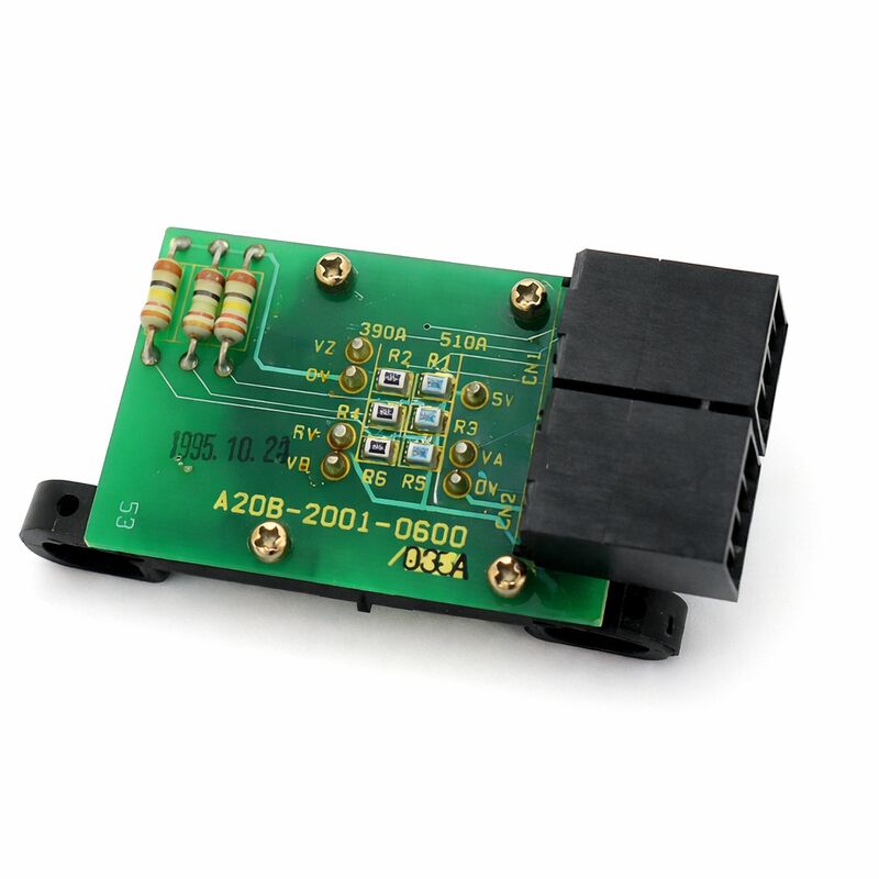
The A20B-2001-0600 is a spindle motor encoder PCB from FANUC's A20B-2001 series — the sensing board that reads the spindle motor shaft's rotation and generates the feedback signals the spindle amplifier needs to control the spindle.
C-signal (speed feedback): The spindle amplifier compares the C-signal's measured speed against the commanded RPM and applies corrective current to close the gap. A degraded C-signal introduces measurement noise into this loop — the amplifier cannot distinguish genuine speed error from sensor noise, so it overcorrects continuously. The result is speed hunting: the spindle oscillates around the commanded RPM rather than holding it steadily, producing surface finish irregularities on the machined part.
Z-signal (orientation reference): One pulse per motor revolution. The CNC uses this pulse as the angular reference for spindle orientation (M19) — the precise stop position required before the tool changer can engage the spindle. When the CNC commands orientation, it decelerates the spindle and latches position at the Z-pulse. No Z-pulse means the spindle cannot orient, the tool change alarms, and production stops.
The two signals fail independently. Loss of Z-signal only: spindle speed is normal, orientation fails. Degraded C-signal only: speed hunting and unstable RPM under cutting load, tool changes still work. These distinct fault patterns are the diagnostic tool that isolates which signal path has failed before any hardware is removed.
Key Specifications
| Parameter |
Value |
| Part Number |
A20B-2001-0600 |
| Series |
A20B-2001 |
| C-signal |
Speed feedback |
| Z-signal |
1 pulse/rev (orientation) |
| Installation |
On/inside spindle motor |
| Operating Temp |
0–55°C |
| Origin |
Japan |
A20B-2001 Series — Suffix Matching Required
The A20B-2001 series covers several spindle encoder board variants for different FANUC spindle motor types and generations. Adjacent variants within the family share the mounting concept but differ in sensing geometry, output signal format, and electrical interface. Fitting the wrong variant — even one that physically mounts on the same motor — produces incorrect speed data or spindle alarms. Confirm the -0600 suffix from the installed board's label. If the label is damaged, identify the variant through the spindle motor's order specification.
Air Gap and the Target Element
The A20B-2001-0600 PCB works with a target element — a disc or magnetic ring coupled to the motor shaft — that is a separate component. When replacing the PCB, the target typically remains in place if undamaged. The air gap between the PCB's sensing elements and the target is critical: too large produces weak signals, too small risks contact with the spinning target.
Confirm the correct air gap per the spindle motor's maintenance documentation after fitting the new board. A correctly functioning PCB fitted at incorrect clearance produces the same weak-signal symptoms as a failed one.
FAQ
Q1: Spindle speed is normal but every tool change fails with an orientation alarm. Does this mean the A20B-2001-0600 has failed?
This symptom pattern — good speed, failed orientation — confirms the Z-signal path is compromised while the C-signal (speed) path is intact. Verify the Z-signal at the encoder connector with an oscilloscope while rotating the spindle: one clean pulse per revolution confirms a working Z-signal. Absent or distorted Z-pulse, with confirmed good cable and connector, confirms the encoder board's Z-signal circuit has failed.
Q2: Spindle speed hunts under cutting load. Power stage appears functional. Could this be the encoder?
Yes. A degraded C-signal introduces noise into the speed feedback loop — the amplifier cannot hold speed steadily because it cannot distinguish real speed variation from measurement noise. Measure the C-signal quality at the encoder connector under load. A noisy or irregular signal with an intact cable confirms the encoder board as the fault source.
Q3: After a spindle crash, orientation sometimes works and sometimes fails. What is happening?
A crash can shift the encoder assembly without fully disabling it, changing the air gap between the PCB sensing elements and the target. An off-tolerance air gap produces a weak, intermittent Z-signal — orientation works when the signal happens to be strong enough, fails when it is not. Inspect the encoder body for displacement from its mounting position and check the target for mechanical damage before replacing the PCB.
Q4: What should be checked before condemning the A20B-2001-0600?
Inspect the encoder cable connector for corrosion, coolant residue, and bent pins. Verify cable continuity, particularly for intermittent opens near the motor end. An intermittent cable fault produces identical symptoms to a failed PCB at a fraction of the replacement cost. If cable and connector are confirmed good and alarms persist, then the encoder board is the fault source.
Q5: Can the A20B-2001-0600 be replaced without removing the spindle motor?
In many machine configurations, the encoder assembly is accessible from the rear of the spindle head or through a service panel, allowing board replacement without full motor removal. If motor removal is required, document all electrical connections and the mechanical installation before starting, and verify spindle motor alignment on reinstallation.

 Your message must be between 20-3,000 characters!