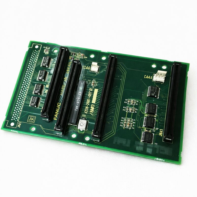
FANUC A20B-2001-0670 | 3-Slot Backplane PCB — Series 20 / 21 CNC Control Rack, Japan Origin
Part Number: A20B-2001-0670
Manufacturer: FANUC Corporation (Japan)
Product Type: 3-Slot Backplane PCB
Board Series: A20B-2001
Compatible Systems: FANUC Series 20, 21 CNC
Slot Count: 3
Overview
The A20B-2001-0670 is a 3-slot backplane printed circuit board for FANUC's Series 20 and Series 21 CNC control racks.
It is the structural and electrical foundation of the controller module assembly: the board onto which the functional PCBs — CPU modules, memory modules, axis control boards, I/O modules — physically mount and electrically connect.
Without the backplane, the individual control boards have no interconnection and the controller cannot function as a system.
FANUC's Series 20 and Series 21 controllers were compact, efficient CNC platforms targeted at single-path machine tools with moderate axis counts.
The Series 21 in particular became one of the more widely adopted FANUC controllers in its class, appearing in turning centres and machining centres around the world.
The 3-slot backplane configuration served configurations requiring a compact module assembly — three slots accommodate the essential modules for a complete controller without the larger rack size of the wider configurations.
The backplane PCB performs two distinct functions in the controller. Structurally, it provides the mechanical connectors that accept each module's edge connector, locking each board securely in its slot and holding it against vibration.
Electrically, it carries the power and communication buses that connect every installed module to every other.
A module in slot 1 communicates with the CPU in slot 2 and the memory in slot 3 through the traces routed across the backplane substrate — none of this communication is cabled.
Key Specifications
| Parameter |
Value |
| Part Number |
A20B-2001-0670 |
| Manufacturer |
FANUC Corporation |
| Product Type |
3-Slot Backplane PCB |
| Board Series |
A20B-2001 |
| Compatible Systems |
FANUC Series 20, 21 CNC |
| Slot Count |
3 |
| Origin |
Japan |
| Operating Temperature |
0 – 55°C |
| Storage Temperature |
−20 – 60°C |
| Humidity |
75% RH max (non-condensing) |
| Condition Available |
New (surplus) / Refurbished / Repaired |
Backplane Function in the FANUC Series 20/21 Architecture
The Series 20 and Series 21 controllers were designed for compact, cost-effective CNC applications.
Their module configuration is deliberate: a small number of modules provides the complete controller function, and the backplane defines how many modules can be accommodated and how they communicate.
The power distribution function is invisible during normal operation but critical.
The controller's power supply feeds regulated voltages — typically +5V, +12V, ±15V, and +24V — to all modules through the backplane's power rails. Every module in every slot draws its supply current from these shared rails.
The backplane's traces are designed for the total current load of a full complement of modules.
A degraded backplane trace can produce unexpected behaviour in multiple modules simultaneously, because the reduced or noisy power supply affects everything connected to the affected rail.
The communication buses on the backplane are equally critical.
The internal address bus and data bus that the CPU uses to access memory, the I/O communication bus that the axis control modules use to exchange data with the CPU — all of these are routed across the backplane.
Any discontinuity in a backplane trace breaks the communication path for every device that depends on that trace.
Backplane Faults — A Distinctive Pattern
Backplane failures have a characteristic diagnostic pattern that distinguishes them from individual module failures. When a single module fails, only the functions served by that module are affected. When the backplane fails, multiple modules fail simultaneously, often in a way that seems inconsistent or unrelated.
A power rail fault on the backplane can produce random alarms across different controller functions — a memory error here, a servo communication fault there, a display corruption somewhere else.
These alarms have no single functional cause in common except that they share the affected power supply.
A trace fault on a communication bus produces bus-level faults: multiple modules that use that bus may all report communication errors or fail to initialise, even though each module is individually functional.
The controller may fail to complete its startup sequence because the CPU cannot communicate with the memory or I/O modules.
When a controller generates multiple simultaneous alarms that span different functional areas, and replacing individual modules does not resolve the problem, the backplane is a strong suspect.
Inspection and Replacement
Backplanes are passive boards — they contain no active components beyond the connectors and the copper trace infrastructure.
Physical damage causes most backplane failures: trace damage from repeated card insertion and removal over many years, moisture ingress that creates corrosion paths across trace runs, or mechanical damage from overtightening of module mounting hardware.
Visual inspection is the first step. Inspect the backplane connectors for bent or damaged pins.
Check the PCB surface for any trace damage, corrosion staining, or delamination near connector areas. Look for signs of past overcurrent events — discolouration or carbonisation near power connector contacts.
Backplane replacement in a Series 20/21 controller requires removing all installed modules, replacing the backplane, and reinstalling the modules.
The backplane slot-to-module assignment must be respected: modules installed in incorrect slots will not function correctly, as the backplane's electrical routing is slot-specific.
FAQ
Q1: After a lightning event, the Series 21 controller shows simultaneous alarms for memory and servo communication, but no individual module appears damaged. Could this be the backplane?
Yes. Lightning transients can damage backplane trace insulation without visibly burning the PCB surface.
The transient energy can track along trace runs, damaging the dielectric at vulnerable points.
With trace damage on a shared bus, multiple modules generate alarms simultaneously even though each module is individually intact.
If module swapping confirms the modules are all functional independently, the backplane is the cause.
Q2: One slot on the backplane produces an alarm regardless of which module is installed in it. The other two slots work correctly with the same modules. Is this the backplane?
A slot-specific fault with multiple confirmed-good modules is a clear backplane fault.
The problem is in the connector for that slot — either a damaged pin, a broken trace between that slot's connector and the bus, or a short in the slot's signal or power wiring. Replace the backplane.
Q3: The controller modules were recently shuffled to check compatibility. After reinstallation, the controller fails to boot. The backplane appeared undamaged during the shuffle. What could be wrong?
Module shuffling can bend connector pins if boards are inserted at angles or with excessive force.
A single bent pin on the backplane connector can prevent one module's connector from making full contact, producing an intermittent or failed communication bus.
Remove all modules, inspect every connector pin on the backplane with a magnifying glass, carefully straighten any bent pins, and reinstall the modules one at a time.
Q4: The backplane's power supply connector area shows mild discolouration. The controller still operates. Should the backplane be replaced?
Discolouration near power connectors indicates a past thermal event — likely a period of excessive current through that contact area.
Even if the controller currently operates, the discolouration indicates that the connector contact resistance has increased at that point.
Increased resistance in a power rail causes voltage drops that worsen under load. Replace the backplane before the degradation causes unexpected controller failures during production.
Q5: The Series 21 controller is being upgraded to a newer FANUC platform. Can the A20B-2001-0670 backplane be retained for use in the new controller?
The A20B-2001-0670 backplane is specific to the Series 20/21 module configuration. Newer FANUC controller platforms use entirely different module formats, connector types, and backplane architectures.
This backplane is not interchangeable with newer systems.
It is useful only as a spare for other Series 20/21 controllers or for the original machine if the upgrade involves installing a complete new control system rather than a board-level upgrade.

 Your message must be between 20-3,000 characters!