FANUC A20B-2001-0700 | Servo Driver Circuit Motor Board — Japan Origin, Discontinued
Part Number: A20B-2001-0700
Manufacturer: FANUC Corporation (Japan)
Product Type: Motor Board / Servo Driver Circuit PCB
Alternate Reference: A16B-2202-0440 / A350-2001-T704/01
Status: Discontinued by Manufacturer
Overview
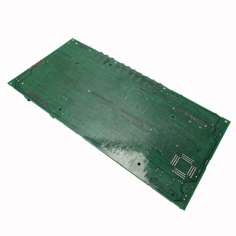
The A20B-2001-0700 is a servo driver circuit PCB — a motor board in FANUC's terminology — used within FANUC servo drive systems.
It is classified as a driver circuit board, which positions it as the component responsible for generating and controlling the switching signals that drive the servo motor's power stage. This is the electronics that directly controls axis motion at the current level.
In FANUC servo amplifier architecture, the servo drive system separates into distinct functional layers.
The CNC controller sends position and speed commands.
The servo amplifier module receives these commands and executes current control through the motor winding. Inside the servo amplifier, the driver circuit PCB is the interface between the control logic and the power transistor stage. The A20B-2001-0700 sits in this layer.
This board is discontinued and carries alternate reference numbers A16B-2202-0440 and A350-2001-T704/01 — both of which may appear on machine documentation, service records, or older FANUC parts lists referring to the same component.
When sourcing, confirm the board against all three references.
Key Specifications
| Parameter |
Value |
| Part Number |
A20B-2001-0700 |
| Manufacturer |
FANUC Corporation |
| Product Type |
Motor Board / Servo Driver Circuit PCB |
| Board Series |
A20B-2001 |
| Alternate Part Numbers |
A16B-2202-0440, A350-2001-T704/01 |
| Function |
Servo drive circuit — switching signal generation |
| Production Status |
Discontinued by Manufacturer |
| Origin |
Japan |
| Operating Temperature |
0 – 55°C |
| Storage Temperature |
−20 – 60°C |
| Humidity |
75% RH max (non-condensing) |
| Condition Available |
New (surplus) / Refurbished / Repaired |
Servo Driver Circuit — Functional Role
The servo motor in a FANUC drive system is an AC motor. Controlling it requires converting the DC bus voltage into a precisely shaped three-phase AC output at variable frequency and amplitude — this is what makes the motor turn at the commanded speed and torque.
The power transistors in the servo amplifier perform this conversion.
The driver circuit board is what tells those transistors when to switch, at what timing, and in what pattern.
Get the switching signals wrong and the motor does not turn correctly.
Get them badly wrong — wrong timing, failure to turn off a transistor at the right moment — and the result is a shoot-through fault: a direct short-circuit condition across the DC bus that destroys the power stage instantly.
The driver circuit is therefore both the performance component and the protection component in the amplifier.
It executes the control algorithm and it monitors for faults that require immediate transistor shutdown.
The A20B-2001-0700 performs these functions within its specific servo amplifier application. Its circuit design is matched to the power transistors and gate drive requirements of the servo amplifier it was designed for.
Multiple Part Number References
Three numbers refer to the same board: A20B-2001-0700, A16B-2202-0440, and A350-2001-T704/01. This situation is common with FANUC servo components. FANUC's part numbering system sometimes assigns different numbers to the same physical board depending on how it is ordered — as a standalone PCB, as part of an assembly, or under an older specification revision.
When a machine's service documentation shows one of these numbers and a supplier lists the board under another, verify that all three numbers resolve to the same physical component before proceeding with a purchase. Misidentification based on partial number matching is a common cause of incorrect parts being ordered for servo system repairs.
Fault Diagnosis Context
Servo driver circuit PCBs typically fail in one of several ways. Thermal stress from sustained high-current operation ages gate drive circuits and optocouplers over time.
A single overcurrent event — from a motor fault, a mechanical jam, or a programming error that commands impossible motion — can destroy gate drive circuits or feedback elements on the driver board without necessarily destroying the power transistors.
When a servo axis shows an alarm that points to the drive circuit rather than the motor or encoder — overcurrent, IPM fault, driver fault alarms — the driver circuit PCB is a primary candidate after the power stage and motor have been checked.
A board fault of this type typically produces consistent alarms at the same operating condition rather than random intermittent faults.
Before replacing the A20B-2001-0700, verify that the cause of the original failure is understood.
A driver circuit board installed into an amplifier with a shorted power transistor stage will be destroyed at the next power-on.
The root cause must be resolved before replacement parts are installed.
FAQ
Q1: The servo axis trips an IPM fault alarm consistently at high speed. Should the A20B-2001-0700 be replaced first?
Not without checking the power stage first. IPM (Intelligent Power Module) fault alarms indicate the IPM has detected an overcurrent or overtemperature condition. The driver circuit PCB sends the gate signals, but the IPM itself monitors and protects. Measure the DC bus voltage, check the motor insulation resistance, and inspect the motor power cable for damage before concluding the driver board is at fault. Replace the driver board only after the power stage and motor have been cleared.
Q2: There are three part numbers for this board. Which one should be used when ordering?
Any of the three — A20B-2001-0700, A16B-2202-0440, or A350-2001-T704/01 — may appear in supplier listings for the same board. Confirm with the supplier that the physical board being supplied matches all three references before ordering. Use the part number from the machine's electrical documentation as the primary search reference.
Q3: Can the A20B-2001-0700 be tested outside the servo amplifier before installation?
Bench-testing a driver circuit PCB in isolation from its amplifier is not straightforward — the board's normal operating conditions require the amplifier power stage and control signals to be present. Most qualified servo repair centres test driver boards within the complete amplifier under controlled conditions. Purchasing from a supplier who tests boards in the relevant amplifier configuration gives better assurance than an untested unit.
Q4: The amplifier blew a fuse after a hard motor fault. Could the driver board be damaged?
Yes. Severe motor faults — winding shorts, mechanical seizure at high speed — produce current spikes that can exceed the driver circuit's design limits even with protection circuits in place. A fuse that blew suggests the event was severe. Inspect both the power transistors and the driver PCB before assuming either is intact. Replace any component that shows visible damage or tests outside specification.
Q5: How should a surplus A20B-2001-0700 be stored before use?
Anti-static packaging is essential — driver circuit PCBs contain gate drive ICs and optocouplers that are sensitive to electrostatic discharge. Store at room temperature in a dry environment away from humidity. Do not store near solvents or corrosive materials. Inspect the board visually before installation after any extended storage period, checking for oxidation on connector contacts and any signs of physical damage from handling or storage conditions.

 Your message must be between 20-3,000 characters!