FANUC A20B-2001-0820 | Alpha SVM1 Servo Amplifier Control PCB — Early Generation, Japan Origin
Part Number: A20B-2001-0820
Manufacturer: FANUC Corporation (Japan)
Product Type: Servo Amplifier Control PCB (Early Generation)
Board Series: A20B-2001
Drive Family: FANUC Alpha Series SVM1 (Single-Axis Servo Amplifier Module)
Generation: Early Alpha series — predecessor to later A20B-2001-093x series
Overview
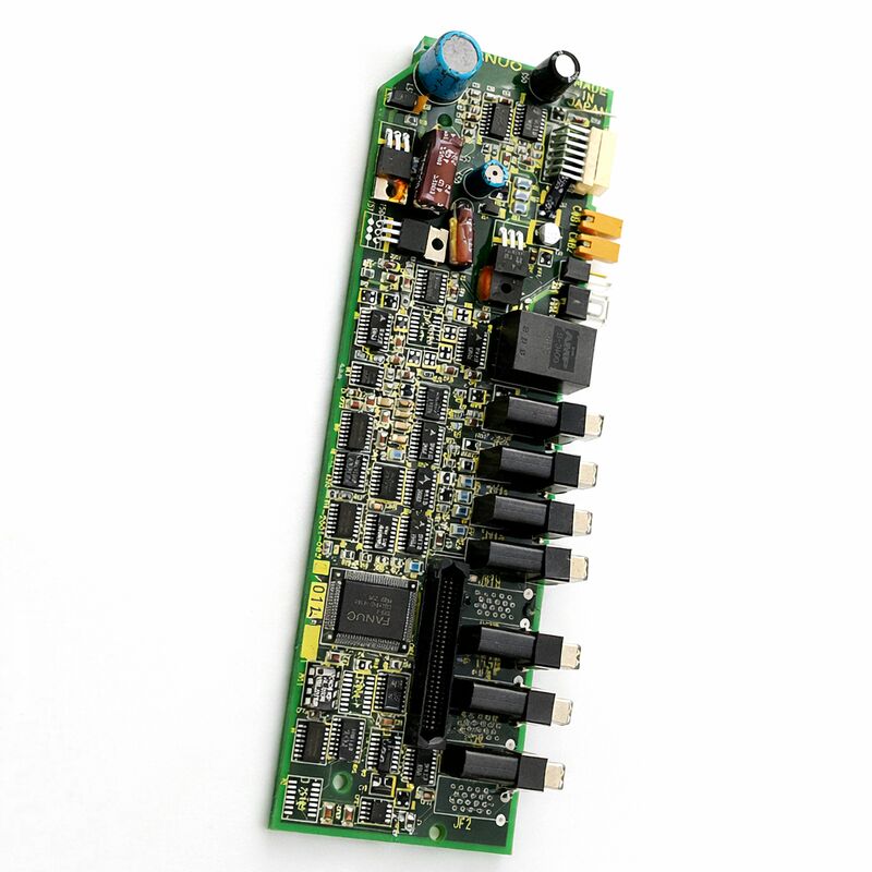
The A20B-2001-0820 is an early-generation control PCB for FANUC's Alpha series SVM1 (Single-Axis Servo Amplifier Module).
It sits at the front face of the SVM1 drive unit — the board that contains the control electronics, DSP servo processing, CNC communication interface, and drive status indicators for a single-axis servo amplifier.
This specific board predates the more widely referenced A20B-2001-093x variants that became the standard across the later Alpha SVM1 range.
FANUC's Alpha servo amplifier system was introduced as a major step forward from the earlier SVU (Servo Unit) range.
The Alpha architecture used a shared DC bus topology — a PSM (Power Supply Module) provided the DC rail, and the SVM modules drew from it to drive individual servo motors.
The SVM1 drove a single servo axis. Each SVM1 unit contained a control board and a wiring/power board.
The control board was the intelligent half: it ran the servo algorithm, communicated with the CNC controller via optical fiber, and provided the gate drive signals to the power transistors in the drive's power section.
The A20B-2001-0820 was the control board for the earliest SVM1 configurations in the Alpha series.
It preceded the revisions that addressed the expanded current range covered by the later -093x boards.
Machines and controllers that were installed with the original Alpha drive system — before the later revisions reached the market — contain this earlier board generation.
These machines are still in service, and when the control board of one of these early SVM1 modules fails, the A20B-2001-0820 is the correct replacement.
Key Specifications
| Parameter |
Value |
| Part Number |
A20B-2001-0820 |
| Manufacturer |
FANUC Corporation |
| Product Type |
Servo Amplifier Control PCB (Early Generation) |
| Board Series |
A20B-2001 |
| Drive Family |
FANUC Alpha SVM1 |
| Generation |
Early Alpha series |
| Interface |
Optical fiber (CNC serial servo communication) |
| Status Display |
LED status indicator |
| Origin |
Japan |
| Operating Temperature |
0 – 55°C (as installed in drive) |
| Storage Temperature |
−20 – 55°C |
| Humidity |
75% RH max (non-condensing) |
| Condition Available |
New (surplus) / Refurbished / Repaired |
Early Generation Alpha — The First SVM Boards
FANUC's introduction of the Alpha series represented a transition from the SVU architecture to the shared-bus SVM/PSM system that became standard.
The early Alpha SVM1 units established the fundamental architecture that remained in use throughout the Alpha series' commercial life.
The control board layout, the optical fiber communication interface, the front-mounted status LED, and the fuse placement were all established with this early generation.
The early generation boards like the A20B-2001-0820 used the same operating principles as their successors: the DSP ran the position, velocity, and current loops simultaneously; the optical fiber link connected to the CNC controller; the power board received gate drive signals from the control board.
These principles were carried forward through all subsequent Alpha SVM versions.
What changed across generations was the specific hardware implementation — the IC generations, the current rating coverage, minor interface refinements.
This continuity means that the diagnostic and maintenance approach developed for later Alpha SVM boards applies equally to machines using the A20B-2001-0820.
The LED status codes follow the same conventions.
The alarm categories — communication errors, gate drive faults, power supply faults — are structured identically.
A technician familiar with later Alpha SVM boards will find the early generation boards immediately familiar.
LED Status Indicators and Fault Diagnosis
The front-mounted LED display on the A20B-2001-0820 is the primary diagnostic reference when the drive produces an alarm.
The display shows a numeric or alphabetic code that identifies the specific fault condition.
These codes map to fault categories described in the Alpha servo amplifier maintenance documentation.
A blank display — no indication at all — means the control board's power supply is not functioning.
This could be a blown fuse on the board, an internal power supply circuit failure, or an absence of the external DC bus voltage that feeds the board's supply circuits.
The Daito fuse on the front face of the board is the first component to check.
A display of "–" (dash) indicates the drive is powered and waiting for the CNC to issue its ready signal. This is normal during the pre-run phase.
A "0" display indicates full drive readiness with the motor energised. Any other display code is an alarm requiring investigation.
Early Generation Boards in the Aftermarket
The A20B-2001-0820 occupies an interesting position in the aftermarket supply chain.
It is old enough that original FANUC stock is exhausted, but the machines it served are not old enough that they have uniformly been replaced.
Many are still running. When the drive control board fails on one of these machines, sourcing a tested replacement requires navigating the surplus and refurbished board market rather than standard distribution channels.
Tested surplus units from decommissioned machines are the most common source.
A professionally refurbished board — where the capacitors and other aging components have been replaced and the board has been functionally tested in an Alpha SVM1 drive unit — is the highest-confidence option. An untested surplus board carries more risk.
The key test for any replacement board is functional testing in an SVM1 drive unit with a real servo motor load. Bench testing with power applied but no motor connected confirms the board powers up and the status display initialises, but does not confirm the current control loops or the feedback processing are working correctly.
Full functional testing requires a drive with a motor.
FAQ
Q1: The Alpha SVM1 drive shows a communication error alarm immediately at power-on. The optical fiber cable is confirmed undamaged. The CNC controller itself is working correctly. Is this the A20B-2001-0820?
A communication error at power-on with a confirmed good fiber cable and working CNC points to the control board's optical receiver circuit.
The board receives the CNC's serial communication through the optical fiber; if the receiver circuit has degraded or failed, the board cannot establish communication with the CNC.
Clean the optical connector port on the board, then retest.
If the alarm persists, the board's receiver circuit has failed and the board requires replacement.
Q2: This is described as an "early generation" board. Is it compatible with all Alpha SVM1 drive unit variants?
The A20B-2001-0820 was fitted in specific SVM1 drive unit variants in the early Alpha series. Whether it is compatible with a specific SVM1 drive unit depends on the drive unit's model number and its corresponding board specification.
The drive unit's documentation or the GE FANUC Alpha amplifier descriptions document lists which control board specification each SVM1 model uses.
Confirm the full SVM1 drive unit model number and verify the correct control board before installation.
Q3: After a machine sat idle for 18 months, the early Alpha SVM1 shows erratic behaviour — sometimes initialising correctly and sometimes producing different alarm codes on consecutive power cycles. Is the board failing?
Erratic and inconsistent alarm codes on an early generation board after extended idle time is consistent with component aging — particularly capacitors on the control board that have dried out during the storage period.
Aged electrolytic capacitors on the control board's power supply section produce unstable supply voltages that cause erratic operation.
A board refurbishment that replaces the electrolytic capacitors and functionally retests the board is the appropriate response before condemning the board entirely.
Q4: Can the A20B-2001-0820 be replaced with the later A20B-2001-0930 board?
These are different board generations within the same A20B-2001 family. Whether the later -0930 is a direct physical and electrical substitute for the earlier -0820 in a specific SVM1 drive unit depends on the drive unit's design.
Some drive unit configurations can accept a later board revision; others have hardware differences that make substitution inappropriate.
Verify with the specific drive unit's documentation or a qualified FANUC drive service specialist before attempting a cross-revision substitution.
Q5: The drive's Daito fuse blew. After replacing it, the board is functional but the same fuse blew again three weeks later. What is happening?
A recurring fuse failure points to a persistent root cause rather than a single event.
Common causes include a failing electrolytic capacitor on the board's power supply that periodically creates a short-duration current spike, a leakage fault in the external DC bus connection that creates a surge when the bus charges, or a weakening gate driver component that draws excessive current under specific operating conditions.
Investigate each of these before replacing another fuse — without addressing the root cause, the replacement fuse will fail again.

 Your message must be between 20-3,000 characters!