FANUC A20B-2001-0821 | Alpha Series SVM Servo Control Board — CNC and Robot, Japan Origin
Part Number: A20B-2001-0821
Manufacturer: FANUC Corporation (Japan)
Product Type: Servo Amplifier Control Board (SVM PCB)
Board Series: A20B-2001
Drive Family: FANUC Alpha Series Servo Amplifier Module (SVM)
Application: FANUC CNC and robot servo drive systems
Overview
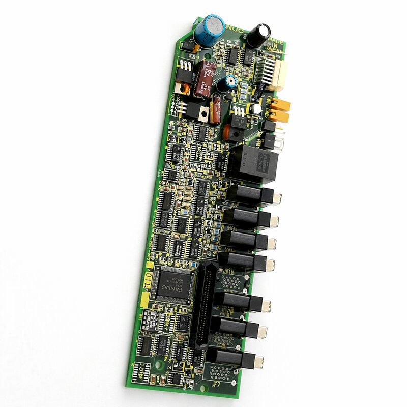
The A20B-2001-0821 is a servo amplifier control board for FANUC's Alpha series Servo Amplifier Module (SVM).
In FANUC's modular Alpha drive architecture, the SVM is the amplifier unit that directly powers a servo motor — taking the DC bus voltage supplied by the PSM and converting it to the three-phase variable-frequency AC that drives the motor.
The A20B-2001-0821 is the control board within the SVM: the PCB that contains the processing electronics for the servo drive's current loop, velocity loop, encoder feedback interface, and CNC communication.
The Alpha series drives were deployed across a wide range of FANUC-controlled machine tools and industrial robots.
In a CNC machining centre, each axis motor has its own SVM. In a six-axis industrial robot, each joint motor has its own SVM or shares an SVM unit with a neighbour.
Every one of these SVMs contains a control board. When a servo drive control board fails, that axis or joint stops — and with the correct replacement board, it restarts.
The A20B-2001 series spans control boards for multiple Alpha SVM configurations, covering different drive current ratings and interface types.
The -0821 variant serves its specific SVM model and hardware revision within this family.
The board is manufactured in Japan and designed for the continuous-duty requirements of industrial servo drive applications.
Key Specifications
| Parameter |
Value |
| Part Number |
A20B-2001-0821 |
| Manufacturer |
FANUC Corporation |
| Product Type |
Servo Amplifier Control Board |
| Board Series |
A20B-2001 |
| Drive Family |
FANUC Alpha Series SVM |
| Application |
FANUC CNC and robot servo drive control |
| Origin |
Japan |
| Operating Temperature |
0 – 55°C (as installed in SVM unit) |
| Storage Temperature |
−20 – 55°C |
| Humidity |
75% RH max (non-condensing) |
| Condition Available |
New (surplus) / Refurbished / Repaired |
The SVM Control Board — Three Loops in One
The servo drive control board executes all three levels of servo feedback control simultaneously. Understanding how these loops work together explains both what makes a well-functioning servo drive perform precisely and what fails when the control board degrades.
The current loop is the foundation.
It reads the motor's phase currents from the SVM's current sensors, compares these to the current commands from the velocity controller, and adjusts the IGBT gate signals to bring actual current to the commanded level. This loop runs at rates in the tens of kilohertz.
A degraded current measurement circuit on the board introduces errors into this loop, producing current distortion that appears as motor noise, vibration, and heat.
The velocity loop sits above the current loop.
It reads the encoder feedback, calculates the actual motor velocity, compares it to the commanded velocity from the position controller, and generates current commands.
This loop updates every few hundred microseconds.
A degraded encoder interface circuit produces noise in the velocity feedback, causing speed instability.
The position loop sits at the top. It receives position targets from the CNC's interpolator and compares them to the actual encoder position.
The position error drives the velocity command. This loop closure happens every servo cycle — typically 1 millisecond.
The accuracy of the machine's axis positioning is ultimately determined by how well all three loops execute together on this control board.
Alpha SVM in CNC and Robot Applications
In a CNC machine tool, the Alpha SVM modules are mounted alongside the PSM in the drive cabinet. Each SVM drives one axis. In a 3-axis machining centre, there are typically three SVMs — one for X, one for Y, one for Z — plus a spindle amplifier module.
The control boards in these SVMs communicate with the CNC through FANUC's serial servo bus, receiving position commands and reporting encoder positions.
In a FANUC industrial robot controller, the same SVM architecture drives the robot's joint motors.
The R-J3 controller generation, for example, used Alpha SVMs for the robot's six joint axes.
The robot controller communicates with these SVMs through the same serial interface as a CNC.
The A20B-2001-0821 control board serves both application contexts because the hardware architecture is consistent.
This cross-application compatibility is a practical advantage in maintenance.
A control board from a retired robot can potentially serve as a replacement in a CNC machine, and vice versa, if the board's full part number matches exactly.
Identifying a Control Board Fault
A servo drive control board fault produces a specific pattern of symptoms that distinguishes it from other drive system faults.
Position errors, velocity instability, or unusual motor noise that appears only on one specific axis — while all other axes operate correctly — points to that axis's SVM control board or its encoder feedback path. Control board problems tend to be axis-specific and consistent.
A drive that refuses to enter its ready state at power-on, showing a VRDY (velocity ready) alarm before any motion is commanded, is a strong indicator of a control board fault.
The board runs self-diagnostics at power-on. A failure in this sequence produces an immediate and persistent alarm.
Intermittent position errors that worsen with temperature — the axis performs correctly when the drive is cold and degrades as it warms up — suggest a thermally sensitive component on the control board reaching the end of its service life.
FAQ
Q1: One CNC axis produces a persistent VRDY alarm at power-on. The DC bus voltage is correct. Other axes are normal. Is this the A20B-2001-0821?
A single-axis VRDY alarm at power-on, with correct DC bus and normal other axes, is consistent with a control board fault.
The board's power-on self-test has failed. Check the SVM's LED indicators for any alarm code.
Confirm the encoder cable and feedback connector are seated correctly — a loose feedback connector can also produce this symptom.
If the cable is confirmed good, replace the control board.
Q2: The axis runs correctly at low speed but shows increasing position error at higher feed rates. The mechanical system appears normal. Could this be the control board?
Increasing position error at high feed rates with a normal mechanical system points to the servo control loops.
The velocity or current loop may not be responding fast enough — a sign that the control board's processing circuits are degraded.
Also check the servo parameters (loop gains, feedforward) to confirm they are correct.
If parameters are correct and the problem persists, the control board's DSP or interface circuits have likely aged.
Q3: The axis motor produces unusual vibration and noise at standstill, but position accuracy is acceptable during motion. What on the control board could cause this?
Vibration and noise at standstill with acceptable accuracy during motion typically indicates a problem in the current loop — specifically the current measurement or gate drive section of the control board.
A small error or noise in the current feedback at standstill produces dithering current that manifests as vibration.
This type of fault often worsens with temperature as components age. Replace the control board and compare the standstill behavior.
Q4: Can a replacement A20B-2001-0821 board from a robot application be used in a CNC machine tool?
If the part numbers match exactly, the hardware is compatible.
The servo control board performs the same function in both CNC and robot applications — the difference is in the controller software and the mechanical system, not the drive board.
Confirm the full part number including the -0821 suffix matches. Never use a different suffix as a substitute, even if the board appears physically similar.
Q5: After control board replacement, the axis overshoots its target position on every move. The parameters were restored from backup. What is the likely cause?
Position overshoot after board replacement with restored parameters typically indicates a servo loop parameter that was not correctly restored.
The position gain, velocity gain, or feedforward compensation value may be incorrect.
Compare each servo parameter for the affected axis against the machine documentation and the backup values.
Also confirm that the encoder type setting is correct — using an incorrect encoder type setting produces incorrect feedback scaling that manifests as overshoot or oscillation.

 Your message must be between 20-3,000 characters!