FANUC A20B-2001-0931 | Alpha Series SVM2 Dual-Axis Servo Drive Control PCB — For A06B-6079 Two-Axis Amplifier Modules, Type-A PWM Interface, CNC Legacy Spare
Overview
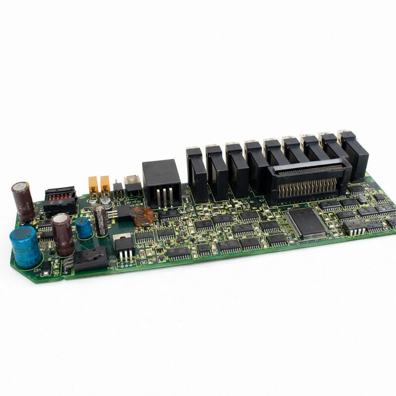
The FANUC A20B-2001-0931 is the control PCB — commonly called the "top card" — for FANUC's Alpha series SVM2 dual-axis servo amplifier family.
The SVM2 (Servo Valve Module, 2-axis) was FANUC's standard dual-axis drive module of the 1990s, widely fitted to machining centres and turning centres as pairs or triples controlling X, Y, and Z axes.
Each A06B-6079 module controls two servo motor axes independently using a common power conversion stage, with the A20B-2001-0931 top card managing both axes' control algorithms simultaneously on a single PCB.
The Type-A interface that the A20B-2001-0931 supports is FANUC's analogue servo command protocol — the predecessor to the FSSB fibre-optic digital bus.
In a Type-A system, the CNC system unit sends each drive module a ±10V analogue velocity command signal for each axis, plus digital enable and reset signals, over a conventional multi-conductor cable.
The control PCB converts these analogue inputs into current loop references, executes the PWM control calculation, and outputs gate drive signals to the power IGBTs.
Encoder feedback from the servo motors returns to the control PCB via a separate feedback cable, completing the position and velocity control loops.
This Type-A interface generation is found on machines manufactured from the late 1980s through the mid-to-late 1990s — still substantial in number in many production environments. When an A06B-6079 drive module develops a control-layer fault, the A20B-2001-0931 top card is the targeted replacement to restore function.
Key Specifications
| Parameter |
Value |
| Function |
Dual-axis servo drive control PCB |
| Compatible Modules |
A06B-6079-H2xx (SVM2 series) |
| Interface |
Type-A analogue PWM |
| Axes Controlled |
2 (simultaneous) |
| Power Board Pair |
A16B-2202-0772 / A16B-2203-0592 |
| Status |
Discontinued spare |
| Origin |
Japan |
The A06B-6079 Module Architecture — Top Card and Base Card
Each A06B-6079 SVM2 module is a self-contained two-axis drive in a single chassis approximately 300mm tall and 80mm wide. Internally, the module splits into two boards connected through a backplane connector:
The base card (A16B-2202-0772 or A16B-2203-0592) is the power processing board — it carries the three-phase rectifier converting AC supply to the DC bus, the DC bus capacitors, the IGBT power modules for both axes, the current sensing circuitry, and the gate driver circuits.
The base card handles all high-power elements and is typically more resistant to failure from electrical causes (though susceptible to thermal stress from inadequate cooling or from motor overcurrent events).
The top card (A20B-2001-0931) is the control and intelligence layer — digital signal processors executing the torque control law, op-amp circuits reading the current feedback from the base card's sensors, encoder data receivers decoding the motor feedback, analogue input circuits receiving the ±10V command from the CNC, and all the communication and status circuitry.
The top card is more exposed to secondary effects of motor faults (through the current feedback signals) and to ageing failures (electrolytic capacitors on its power supply rails).
Type-A Interface — Command and Feedback Wiring
In a Type-A servo drive installation, the wiring between the CNC system unit and the A06B-6079 module passes through a standard 50-pin D-sub or equivalent multi-conductor cable carrying:
Command signals: Analogue velocity references (±10V, one per axis), direction signals, enable signals, and position encoder output signals (if the CNC uses the drive module as a position counter).
Feedback signals: Motor encoder serial data (FANUC serial encoder protocol, single-cable serial), motor brake control signals, drive alarm output signals.
The Type-A architecture's reliance on analogue command signals makes it sensitive to cable integrity: connector pin corrosion, shield continuity breaks, and EMI coupling from adjacent power cables all appear as positioning errors, velocity oscillations, or intermittent servo alarms.
Before condemning an A20B-2001-0931 board, the command cable's shield continuity, connector cleanliness, and signal amplitude at the drive connector should be verified.
Diagnostic Approach — Isolating the Top Card as the Fault Source
When an A06B-6079 module presents alarm codes, the responsible board must be identified before ordering a replacement.
The top card (A20B-2001-0931) is the more likely culprit for:
Communication-type alarms — the card's serial encoder receiver, command cable receiver, and CNC interface circuitry are all within the top card's electronics.
Current control alarms (servo alarm 8, 9, A, 4, 5, 6) — where the control loop itself cannot regulate current correctly, caused by failed op-amps, ADCs, or DSP components on the top card.
"Both axes failed simultaneously" — since both axes share the single top card, a top card failure simultaneously disables both axes of the module.
A base card failure typically affects one axis (one set of IGBTs) while leaving the other functional.
The base card is more likely responsible for: overcurrent trips correlated with specific load conditions, DC bus voltage faults, and single-axis failures where one phase or one axis's IGBTs have failed.
FAQ
Q1: The A06B-6079-H206 module shows alarm "SV-8" on both L and M axes simultaneously. Does this indicate a top card failure?
A simultaneous alarm on both axes of a single SVM2 module strongly suggests the top card (A20B-2001-0931), since both axes share the single top card's encoder receive and control circuits.
If the same alarm appears on drives attached to a different pair of encoder cables — confirming the cables and encoders are functional — the top card is the primary suspect.
Fitting a known-good A20B-2001-0931 top card to the suspect module (with power off and bus discharged) resolves the diagnosis definitively.
Q2: Can the A20B-2001-0931 from an SVM2-20/20 module be used in an SVM2-40/40 module?
The A20B-2001-0931 is the common top card across multiple A06B-6079 SVM2 variants — it appears in both H203 (SVM2-20/20) and H206 (SVM2-40/40) and other variants.
The top card's control and communication functions are identical across these models; the axis current rating is determined by the IGBT modules on the base card, not by the top card.
An A20B-2001-0931 from a functional 20/20 module can therefore be used to test or replace the top card in a 40/40 module.
Confirm by checking the specific FANUC maintenance manual for the A06B-6079 series to verify the top card part number matches across the intended variants.
Q3: After fitting a replacement A20B-2001-0931, the servo still alarms on startup. What are the likely causes?
After top card replacement, check:
(1) all connectors between the top and base card are fully and correctly seated — misaligned connector pins cause false alarms;
(2) the replacement card's encoder feedback cable connections are in the correct sockets — the L-axis and M-axis encoder connectors must match the cable labelling;
(3) axis parameters on the CNC may need verification — if the replacement board has a different firmware revision, parameters may require confirmation or reloading from backup;
(4) the base card's power supply rails should be measured at the top card connector — if the +5V or ±15V rails from the base card are outside specification, the top card's circuits cannot function correctly even if the card itself is good.
Q4: How should the A20B-2001-0931 be packaged for return to a repair centre, and what information should accompany it?
The board should be placed in an ESD-safe antistatic bag (not ordinary plastic), then padded against physical impact inside a rigid box.
The following information helps repair centres test and calibrate the board correctly: the complete drive module order number (A06B-6079-Hxxx), the machine type and CNC control series, the specific alarm codes that appeared before the board was removed, and whether the fault was constant or intermittent.
Some repair centres request the base card's information as well, since top card firmware and calibration settings sometimes depend on the base card revision.
Q5: What is the expected service life of a refurbished A20B-2001-0931, and what typically fails first?
The primary lifespan-limiting components are the electrolytic capacitors on the board's internal power supply section — these degrade through electrolyte evaporation and heat cycling, typically showing measurable capacity reduction after 10–15 years of continuous industrial service at elevated ambient temperatures.
A refurbished board with full capacitor replacement from a reputable FANUC repair centre should deliver 5–10+ years of additional service in a well-maintained drive cabinet at normal operating temperatures.
Secondary failure points include the encoder data receiver optocouplers (which can degrade if the encoder cable has poor shielding and has been carrying high-frequency interference), and the analogue op-amps in the current feedback path (susceptible to ESD damage during servicing).

 Your message must be between 20-3,000 characters!