FANUC A20B-2001-0933 | Alpha Series SVM2-40/80 Servo Amplifier Drive Board — For A06B-6079-H20x Series, 2-Axis, Type A/B Interface, CNC Discontinued Spare Part, Japan Origin
Overview
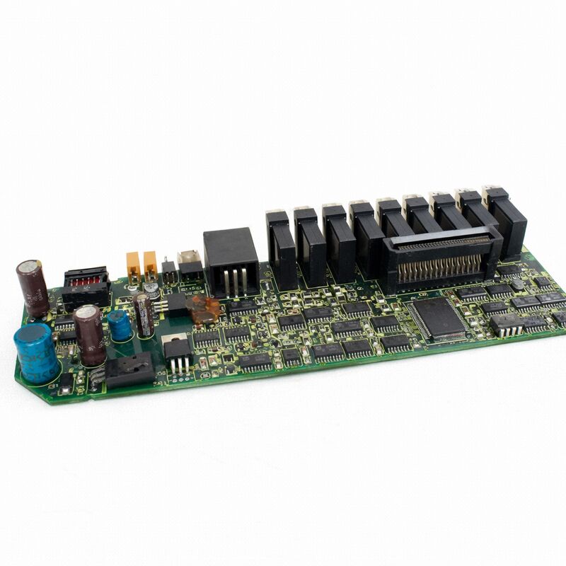
The FANUC A20B-2001-0933 is the control PCB for the Alpha series SVM2 dual-axis servo amplifier modules in the 40A to 80A current range — the drives that power the larger Alpha series servo motors on CNC machine tools and related automation systems.
The A20B-2001-093x board family (with -0931, -0933, and related sub-variants) covers the SVM2's mid-to-high current ratings, handling the axis control functions for the dual-channel drives used to run servo motors in the α12/2000 and α22/2000 class.
Within the A06B-6079 Alpha servo module range, the SVM2 (Servo Valve Module, 2-axis) represents the dual-axis configuration — sharing one common power supply section between two independent servo axis drives.
The A20B-2001-0933 is the control intelligence that makes both axis drives work simultaneously and independently: two separate servo control loops, two sets of encoder feedback receivers, two sets of gate drive outputs, two alarm monitoring circuits — all managed by this one control board.
Understanding the A20B-2001-0933's position within the SVM2 requires knowing how these modules are structured physically.
The SVM2 module contains at minimum two distinct board types: the control/drive board (the A20B-2001-0933) and the wiring board (A16B-2202-0775, A16B-2203-0595, or similar, depending on the specific H-number variant).
The control board provides the intelligence; the wiring board provides the power interface — the current-sense resistors, the gate drive connections to the IPM transistors, and the connector interface to the external wiring. Together they form the complete servo axis drive electronics within the module's aluminium chassis.
Key Specifications
| Parameter |
Value |
| Function |
Dual-axis servo amplifier control PCB |
| Drive Range |
SVM2-40/80, -80/80, -40L/40L |
| Compatible Series |
A06B-6079-H205 through H209 |
| Interface |
Type A and Type B compatible |
| Axes |
2 independent servo axes (L and M) |
| Status |
Discontinued by manufacturer |
| Origin |
Japan |
The SVM2's Place in the Alpha Servo Architecture
The Alpha series servo amplifier system uses a shared DC bus architecture — the PSM (Power Supply Module) provides rectified DC power to the common bus rail, and the individual SVM modules draw from this rail to power their respective motor phases.
This shared bus design means that the PSM must provide enough total current capacity for all connected SVM and SPM (spindle) modules simultaneously, but the individual SVM modules themselves are relatively compact because they only need to handle the switching and current control for their own axes.
The SVM2 with the A20B-2001-0933 control board sits in the higher-current portion of the SVM2 range.
Where the smaller SVM2 variants (H201 through H204, using the A20B-2001-0931 control board) handle axes with lighter servo motors, the SVM2-40/80 and -80/80 variants using the -0933 board drive significantly larger motors — servo motors rated at 40A or 80A peak current per axis.
These drives are found on the heavier axes of large machining centres, boring mills, horizontal machining centres, and similar machines where axis loads and accelerations demand high motor torque and therefore high peak current.
Type A and Type B Interface — Dual Compatibility
One of the A20B-2001-0933's design features is its compatibility with both Type A (analogue ±10V) and Type B (PWM) command interfaces from the CNC axis control board.
This dual compatibility was important during the transition period when FANUC was moving its CNC generations from the older analogue Type A interface to the newer PWM Type B interface:
Type A: Used with FANUC Series 0C, 15A, 15B, 16A, 16B, 18A, and 21TA — the CNC's axis card sends a ±10V analogue signal proportional to the commanded velocity.
The SVM2 control board receives this analogue signal and converts it to the current reference for the servo loop.
Type B: Used with FANUC Series 0 Model D and later Series 16B Type B variant controls — the CNC sends a PWM signal at a fixed carrier frequency, with duty cycle proportional to commanded velocity.
The SVM2 control board demodulates this to extract the velocity reference.
A dip switch on the SVM2 module selects which interface type the drive will use.
This switch must be set correctly for the CNC interface in use — an incorrect setting causes a VRDY OFF alarm immediately on power-up.
NV-RAM — The Critical Parameter Store
The A20B-2001-0933 contains an NV-RAM (non-volatile RAM) chip that stores the motor type and axis-specific parameters for the SVM2's servo loops.
This parameter set defines the motor model, the current limit, the encoder resolution, the velocity loop gain, and other drive-specific settings.
These parameters must match the specific servo motors connected to the drive.
When replacing a failed A20B-2001-0933 with a replacement board:
The NV-RAM chip from the original board can often be transferred to the replacement board if the original board's failure was a circuit fault rather than NV-RAM data corruption.
This preserves the motor parameters in a single step.
Alternatively, parameters can be re-entered manually using the four front-panel buttons (MODE, UP, DOWN, DATA SET) with the motor type number from the motor nameplate and the parameter tables in the Alpha series maintenance manual.
FAQ
Q1: The SVM2 module shows an alarm LED and the axis has failed, but the other axis on the same module is working. Is the A20B-2001-0933 board the cause?
A single-axis fault on one of the SVM2's two axes (L or M) while the other axis operates normally is more likely a fault in that axis's IPM transistor module, wiring board current-sense circuit, encoder cable, or motor — rather than the control board, which handles both axes.
If the control board fails, both axes typically alarm simultaneously because the common control circuitry has failed. Isolate the fault by verifying the encoder cable and connector for the affected axis first (most common single-axis fault source in Alpha drives), then check the IPM for that axis.
The control board becomes suspect when both axes fail simultaneously without any mechanical cause.
Q2: Can the A20B-2001-0933 be used in any A06B-6079 module, or only specific H-number variants?
The A20B-2001-0933 is specified for particular SVM2 variants — the H205, H206, H207, H208, and H209 in the 40A–80A current range.
Lower-current SVM2 variants (H201 through H204) use the A20B-2001-0931 control board.
The current scaling in the control board's current feedback circuits is set for the higher-current range — using the -0933 in a low-current module or the -0931 in a high-current module would result in incorrect current limit settings and abnormal servo behaviour.
Always match the control board to the specific A06B-6079-HXXX module it is installed in.
Q3: After replacing the A20B-2001-0933, the drive generates an immediate servo alarm on power-up. What is the most common cause?
The most common cause is an incorrectly set Type A/Type B interface dip switch. Verify that the interface selection switch on the SVM2 module matches the CNC interface in use — Type A for analogue 16A/18A/0C systems, Type B for the appropriate Type B interface CNC variants.
The second most common cause is incorrect motor parameters in the replacement board's NV-RAM — if the default or wrong motor parameters are loaded, the servo loop will be incorrectly tuned for the connected motor and will alarm immediately.
Check the switch setting and verify the motor type parameters match the connected servo motor's specification.
Q4: The SVM2 module gets very hot during operation. Is this a control board issue?
Heat generation in an SVM2 module is primarily from the power section (IPM transistors) rather than the control board. The control board operates at low power and runs cool.
If the module is running significantly hotter than normal, the causes are typically: degraded thermal interface between the IPM and the heatsink (thermal paste dried out, need replacement); a partially shorted IPM drawing more current than normal; or a cooling airflow problem (blocked filter, failed fan).
These are power section issues. A control board fault rarely causes unusual heat generation; it more typically causes incorrect servo behaviour or alarms.
Q5: Is it possible to test an A20B-2001-0933 board before installing it in a production machine?
Reliable testing of a servo amplifier control board requires a compatible test rig — specifically, a matched SVM2 module power section (or the complete SVM2 drive), a matched Alpha servo motor, and a compatible FANUC CNC or test jig that can send servo commands and verify the axis response.
Bench testing the A20B-2001-0933 in isolation (outside the complete SVM2 module) is not practical for verifying servo performance.
For production-critical applications, sourcing the control board from a specialist repair centre that has tested it on a complete SVM2 test rig with an appropriate Alpha servo motor provides the highest confidence before installation.

 Your message must be between 20-3,000 characters!