FANUC A20B-2001-0750 | Alpha Series A06B-6079 Servo Drive Control PCB — Multi-Axis SVM, Japan Origin
Part Number: A20B-2001-0750
Manufacturer: FANUC Corporation (Japan)
Product Type: Servo Amplifier Control PCB (Drive Board)
Board Series: A20B-2001
Drive Family: FANUC Alpha Series A06B-6079 SVM (Servo Amplifier Module)
Application: FANUC CNC multi-axis servo drive control
Overview
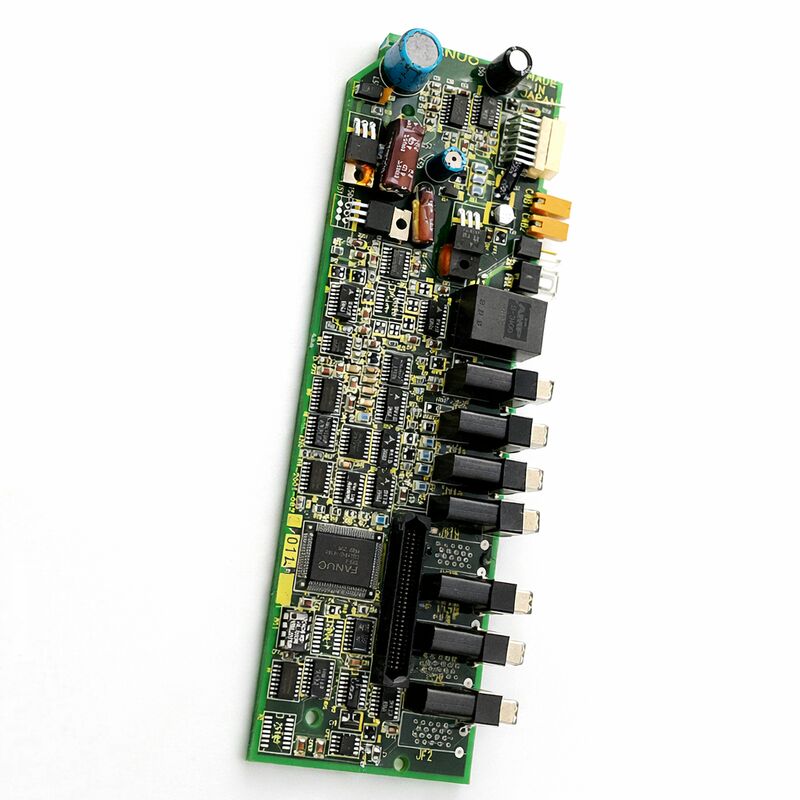
The A20B-2001-0750 is a control PCB from the A20B-2001 series — the family of control boards used inside FANUC's Alpha series A06B-6079 servo amplifier modules.
The 6079 series is FANUC's Alpha SVM (Servo Amplifier Module) product line, used across a wide range of FANUC CNC machine tools and industrial automation systems to drive AC servo motors.
This control board is the front-mounted PCB of the SVM unit: the board that processes the CNC's servo commands, manages the multi-axis position and current loops, interfaces with encoder feedback, and displays the drive's operational status.
In the 6079 SVM architecture, every servo amplifier module contains two PCBs working in tandem.
The control board — the A20B-2001 series — handles all the intelligence: the DSP processing that runs the servo control algorithms, the serial communication interface to the CNC controller via FANUC's optical fiber cable, and the gate drive signals that tell the power transistors when to switch.
The power board (from the A16B-2202 or A16B-2203 series) handles the high-current side of the drive, converting DC bus voltage into motor current. Together, these two boards constitute the complete drive unit.
When the control board fails, the drive cannot execute its servo functions regardless of the power board's condition.
The A20B-2001-0750 belongs to this established control board family. It sits at the front face of the 6079 SVM module, accessible without removing the drive from the cabinet. On its front face is a 7-segment LED status indicator — the first diagnostic tool a technician uses when a servo alarm occurs.
This display shows the drive's operating state codes and alarm numbers, identifying the fault without requiring additional test equipment.
Key Specifications
| Parameter |
Value |
| Part Number |
A20B-2001-0750 |
| Manufacturer |
FANUC Corporation |
| Product Type |
Servo Amplifier Control PCB |
| Board Series |
A20B-2001 |
| Drive Family |
FANUC Alpha Series A06B-6079 SVM |
| Interface |
Optical fiber (FANUC serial servo communication) |
| Status Display |
7-segment LED indicator |
| Origin |
Japan |
| Operating Temperature |
0 – 55°C (as installed in drive) |
| Storage Temperature |
−20 – 55°C |
| Humidity |
75% RH max (non-condensing) |
| Condition Available |
New (surplus) / Refurbished / Repaired |
The Alpha SVM — Drive Architecture
FANUC's Alpha SVM uses a split-board design that reflects the very different operating environments of the control electronics and the power electronics. The power section — IGBTs, DC bus connections, current sensors — operates at voltages up to 325V DC and handles currents measured in tens of amperes. These high-power circuits generate switching noise and heat.
The control section — the A20B-2001-0750 — operates entirely on low-voltage logic supplies. Its circuits are sensitive to the noise and thermal stress of the power section. Separating them onto two distinct boards, with defined interface points between them, is both good engineering practice and a maintenance convenience: it allows the two boards to be replaced independently.
The control board receives the CNC controller's position commands via the optical fiber serial interface. Optical fiber is immune to the electromagnetic interference generated in the drive cabinet — a key reason FANUC chose fiber optic for the CNC-to-drive communication link.
The control board converts these commands into the PWM (pulse-width modulation) gate drive signals that control the IGBT switching in the power section.
Simultaneously, it processes the encoder feedback from the servo motor and runs the position, velocity, and current loops that achieve precise axis positioning.
7-Segment Status Display and Drive Diagnostics
The LED status display on the front of the A20B-2001-0750 is the primary diagnostic interface for the 6079 SVM. It shows a numeric or alphabetic code that identifies the drive's current state:
When the display shows a dash (–), the drive's control power is present but it is waiting for the ready signal from the CNC.
This is normal during the pre-run phase before the CNC completes its startup. When the display shows "0", the drive is fully ready and energising the motor. Any other display indicates an alarm condition specific to the shown code.
This display is particularly valuable because it distinguishes control board faults from power board faults.
Faults that originate in the control board's own circuits — communication errors, internal supply failures, DSP faults — produce specific alarm codes that differ from the overcurrent, overvoltage, and transistor protection alarms that typically originate from the power section.
Reading the alarm code precisely guides the maintenance decision: control board replacement versus power board replacement versus an investigation of the external motor or wiring.
Fuse and Protection Components
The A20B-2001-0750 carries a Daito LM32 fuse that protects the control board's power supply circuits.
This fuse is accessible on the front face of the board without disassembly. If the control board's power supply has been subject to a voltage transient or overcurrent event, the LM32 fuse is the first component to check.
A blown fuse can produce a blank display (the board appears dead) even though the drive's power circuits are intact.
The fuse is replaceable. After replacing a blown fuse, the root cause of the overcurrent event should be investigated before restoring power, since a recurring fuse failure indicates a fault in the circuit the fuse is protecting rather than a component aging event.
FAQ
Q1: The 6079 SVM module shows a blank 7-segment display but the DC bus is confirmed correct. The other drives in the cabinet are operational. Is this the A20B-2001-0750?
A blank display with confirmed DC bus and operational neighbouring drives is consistent with a control board power supply failure.
Check the Daito LM32 fuse on the front face of the board first. A blown fuse produces this exact symptom.
If the fuse is intact and the display remains blank, the control board's internal power supply circuit has failed and the board requires replacement.
Q2: The drive alarm shows a servo communication error code. The optical fiber cable tests as undamaged. What should be checked next on the control board?
Communication error alarms with a confirmed good fiber cable can indicate a degraded optical receiver circuit on the control board.
The receiver converts optical pulses to electrical signals; aging or contamination of the optical connector can reduce received signal strength below the threshold the receiver circuit requires.
Clean the optical connector port on the board with appropriate optical fiber cleaning tools and re-test.
If the alarm persists, the board's receiver circuit has failed.
Q3: After replacing the A20B-2001-0750, the drive initialises but the axis positioning accuracy has degraded. Parameters were restored from backup. What else could explain this?
Degraded positioning accuracy after board replacement with correct parameters typically indicates an encoder feedback circuit issue.
The new control board's encoder interface may be processing signals slightly differently from the original, particularly if there is any marginal signal quality in the encoder cable.
Check the encoder cable shielding and connector contacts.
Also verify that the servo parameters for this axis — particularly the velocity gain and position gain — were correctly restored, as small parameter differences can produce noticeable accuracy changes.
Q4: The drive shows an overvoltage alarm on deceleration, but this alarm is new — the same deceleration profile ran without faults for years. Could the A20B-2001-0750 be causing false overvoltage alarms?
The overvoltage alarm monitors the DC bus voltage through a circuit that includes the control board's voltage measurement path.
A degraded voltage measurement circuit on the control board can produce false overvoltage readings.
Compare the drive's internal bus voltage reading (shown on the CNC's drive diagnostic screen) with the actual bus voltage measured at the bus terminals.
If they differ significantly, the control board's voltage measurement circuit is likely degraded.
Q5: The A20B-2001-0750 replacement was successful but the motor produces unusual noise at low speeds that was not present before. What could be happening?
Low-speed motor noise after a control board replacement suggests a current loop tuning issue.
The current loop regulator gains are set through servo parameters, and a mismatch between the parameter values and the new board's hardware characteristics can produce current ripple at low speeds.
Verify the current loop gain parameters match the motor's specifications.
Also check that the board's hardware revision is the same as the original — different hardware revisions within the same board series can have different gain settings requirements.

 Your message must be between 20-3,000 characters!