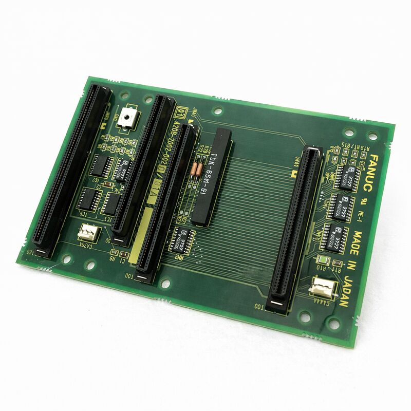
FANUC A20B-2002-0020 | 3-Slot Backplane PCB — Series 16 / 18 CNC, Japan Origin
Part Number: A20B-2002-0020
Manufacturer: FANUC Corporation (Japan)
Product Type: Backplane PCB — 3-Slot Rack Interface
Board Series: A20B-2002
Compatible Systems: FANUC Series 16 / 18 CNC and compatible
Overview
The A20B-2002-0020 is a 3-slot backplane printed circuit board for FANUC Series 16 and 18 CNC systems. It is the structural and electrical foundation of the controller rack — the board that all the other boards plug into.
The main CPU board, the power supply unit, and the option boards occupy the three slots provided by this backplane. Every signal and power connection between these boards passes through the A20B-2002-0020.
Backplane boards are easily overlooked in CNC maintenance because they rarely fail. They contain no active processing components — no CPUs, no memory, no programmable logic. Their function is passive: carry signals and power from one connector position to another, mount the active boards securely in their slots, and maintain the physical alignment of the rack assembly.
This passive nature is also why failures are relatively infrequent. But when they do fail — through physical damage, connector wear, or contamination — the effects are system-wide. Every board in the rack is affected simultaneously.
The A20B-2002-0020 is the specific 3-slot variant in the A20B-2002 backplane series for Series 16/18 controllers.
The three slots accommodate the main CPU board, the power supply board, and one additional option card position.
This configuration covers the standard Series 16/18 system layout.
Key Specifications
| Parameter |
Value |
| Part Number |
A20B-2002-0020 |
| Manufacturer |
FANUC Corporation |
| Product Type |
Backplane PCB |
| Slot Count |
3 |
| Board Series |
A20B-2002 |
| Compatible Systems |
FANUC Series 16 / 18 CNC |
| Boards Hosted |
Main CPU, PSU, option card |
| Design |
Passive signal and power distribution |
| Origin |
Japan |
| Operating Temperature |
0 – 55°C |
| Storage Temperature |
−20 – 60°C |
| Humidity |
75% RH max (non-condensing) |
| Condition Available |
New (surplus) / Refurbished / Repaired |
What a Backplane Does
A FANUC CNC controller is not a single board. It is a collection of boards mounted in a rack, each performing a specific function. The main CPU board handles motion computation. The power supply board converts incoming voltages to the regulated levels the logic boards require. Option boards — servo interfaces, I/O modules, communication boards — add specific capabilities.
These boards communicate with each other continuously.
The CPU sends commands to the servo interface. The servo interface returns position data. The power supply reports status. All of this communication travels across the backplane's copper traces and connectors.
The backplane also distributes power.
The power supply board outputs regulated voltages to the backplane bus. All boards drawing from these voltages receive them through the backplane. This central power distribution keeps individual boards from needing their own power connections — they plug into the backplane and draw what they need.
Physical support is the third function.
The backplane provides the mechanical retention for each board, holding it in position and maintaining the connector engagement under vibration.
CNC machine tools vibrate during operation — the machining process, the coolant pump, the chip conveyor, and the machine's own motion all contribute.
The backplane must maintain secure board engagement through this vibration for the service life of the machine.
Backplane Failures — Rare but System-Wide
Most backplane faults originate in the connector positions — the female connectors that receive each board's edge connector. These connectors experience thousands of insertion and removal cycles over the life of the machine as boards are replaced, inspected, and reinstalled. The contacts wear.
They develop high-resistance points that cause intermittent faults, or they become damaged and produce permanent connection failures.
Physical damage to the PCB itself — cracks from impact, trace damage from tools, or corrosion from coolant ingress — can sever signal paths. Because the backplane routes signals between all boards, a broken trace between two boards affects the communication path between those boards specifically.
Contamination is the other common fault mechanism.
Coolant mist in the controller cabinet settles on circuit boards over time. On the backplane, contamination between the connector contacts can create partial short circuits or increase contact resistance to the point of signal degradation.
Replacement Considerations
Replacing a backplane requires removing all boards from the rack first. The installed boards — CPU, PSU, option cards — must be removed carefully, with their connectors tracked so they are returned to the correct positions.
After the backplane is replaced and the boards are reinstalled, confirm that every board is fully seated before powering on.
A partially seated board produces a fault on that board's communications path.
Since all communications on this backplane pass through the A20B-2002-0020's connectors, a board that is not fully engaged will generate alarms for the signals that run through the faulty contact.
The same software and data considerations that apply to any controller maintenance apply here. Take a full backup of all controller data before beginning any work on the controller rack.
FAQ
Q1: Multiple unrelated alarms appeared simultaneously after a power cycling event. Could the backplane be at fault?
Multiple simultaneous alarms across different board functions are consistent with a backplane fault — specifically, a power distribution or bus communication issue.
A single board failure typically produces alarms related to that board's function only.
If the CPU, PSU, and option board are all showing alarms at once, the common element between them — the backplane — is the logical starting point.
Also check the power supply output voltages before concluding the backplane is at fault.
Q2: One specific communication path between two boards fails intermittently. All other functions are normal. Is this a backplane issue?
Intermittent failure between two specific boards — while all others communicate correctly — points to the backplane connectors for those two boards specifically, or to the trace that routes signals between those connector positions.
This is more specific than a general backplane failure and may be repairable by cleaning and treating the affected connector contacts.
If the intermittent fault persists after connector maintenance, the backplane may need replacement.
Q3: Coolant was found inside the controller cabinet. Several boards were cleaned. Should the backplane also be inspected and cleaned?
Yes. The backplane is mounted in the same cabinet as the other boards and is exposed to the same contamination.
Clean the backplane connector positions carefully with electronics-safe contact cleaner, paying specific attention to the connector pin areas where coolant can bridge adjacent contacts.
After cleaning, inspect visually under magnification before reinstalling any boards.
Do not power on until the backplane is thoroughly dry.
Q4: How is the 3-slot A20B-2002-0020 different from other A20B-2002 backplane variants?
The A20B-2002 series includes backplanes with different slot counts — 1-slot, 2-slot, and 3-slot variants — matching different controller configurations.
The -0020 specifically provides three slots for the standard Series 16/18 configuration. Installing a backplane with a different slot count may not accommodate all required boards.
Confirm the slot count of the existing backplane from its label before sourcing a replacement.
Q5: After a backplane replacement, one board shows a fault that did not exist before. The board was confirmed working in the old backplane. What went wrong?
A fault that appears on a previously working board after backplane replacement points to an installation issue — either the board is not fully seated in the new backplane's connector, the connector contacts are damaged or misaligned in the new backplane, or the board was damaged by electrostatic discharge during handling.
Power off, reseat the affected board firmly, and retest.
If the fault persists, inspect the connector position on the new backplane for damage.

 Your message must be between 20-3,000 characters!