FANUC A20B-2002-0030 | Alpha Series SVU1 Servo Amplifier Control PCB — For A06B-6089-H101/H102, SVU1-12 and SVU1-20, Type-B Interface, Wiring Board A16B-2202-0950
Overview
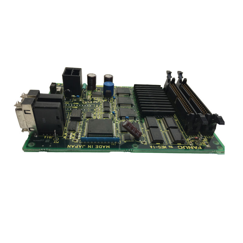
The FANUC A20B-2002-0030 is the control PCB for FANUC's Alpha series SVU1 (Servo Valve Unit 1, single-axis) servo amplifier.
The A06B-6089 SVU series occupies a different design philosophy from the A06B-6079 SVM modular series: while the SVM modules are designed to sit in a shared power supply rack with multiple drive modules sharing a common DC bus, the SVU units are standalone — each unit has its own built-in power supply (rectifier and capacitors), its own regenerative discharge circuit, and its own control electronics.
This standalone architecture allows SVU units to be mounted remotely from the main controller cabinet, closer to the servo motors they drive, with only the CNC command cable and AC power cable needing to reach the unit.
The control PCB (A20B-2002-0030) is the intelligence layer inside the SVU unit. It receives the servo commands from the CNC's axis control board through the Type-B interface — an analogue signal format where the CNC outputs PWM signals (rapid on/off pulses at a duty cycle proportional to the commanded speed) rather than the ±10V analogue velocity reference used in Type-A systems.
The control PCB demodulates these PWM commands back to velocity references, executes the current and velocity control loop, and outputs gate drive signals to the SVU's IPM (Intelligent Power Module) or IGBT power stage.
The A20B-2002-0030 is shared across both the H101 (SVU1-12, 3A axis) and the H102 (SVU1-20) single-axis amplifier variants.
The same PCB part number covers both because the control algorithm and interface circuitry are identical — only the wiring board (A16B-2202-0950 for H101 vs -0951 for H102) and the power stage IPM differ between the two models.
Key Specifications
| Parameter |
Value |
| Function |
SVU1 servo amplifier control PCB |
| Compatible Drives |
A06B-6089-H101 (SVU1-12), H102 (SVU1-20) |
| Interface |
Type-B analogue PWM |
| Wiring Board |
A16B-2202-0950 / -0951 |
| Also Fits |
A06B-6090-H002/H003 (SVUC1) rev /03B+ |
| Status |
Discontinued spare |
| Origin |
Japan |
Type-B Interface — How the SVU Receives Commands from the CNC
The Type-B interface is a FANUC-proprietary analogue servo command system used in the Series 0 Model D, Series 16, and Series 18 CNC controls of the 1990s.
Understanding how it works clarifies why the A20B-2002-0030's control PCB circuitry looks the way it does — and why the Type-B SVU cannot be directly connected to a modern FSSB-based CNC without a system-level hardware change.
In Type-B, the CNC's axis control board outputs a PWM signal for each axis — a square wave at a fixed carrier frequency with a duty cycle proportional to the commanded velocity. A 50% duty cycle represents zero speed command; duty cycles above 50% represent positive direction motion, below 50% represent negative direction.
The SVU control PCB (A20B-2002-0030) receives this PWM signal through the command cable, uses an internal demodulator circuit to extract the analogue velocity reference from the duty cycle, and feeds this reference into the velocity control loop.
This contrasts with the Type-A interface (used in the earlier A06B-6079 SVM2 and other A06B-6096 FSSB modules) where the CNC outputs an analogue ±10V signal directly.
Type-B's PWM approach is more noise-immune over long cable runs (a digital signal versus an analogue voltage), which is why Type-B was the preferred interface for SVU units mounted remotely in the machine's mechanical enclosure rather than adjacent to the main CNC cabinet.
SVU Architecture — Standalone Operation and Remote Mounting
The SVU unit's standalone power supply design — each unit carrying its own rectifier, DC bus capacitors, and in smaller models (H101, H102) a built-in regenerative resistor — is what enables remote mounting. In practical machine tool installation, this means:
An SVU1-12 (H101) can be mounted inside the machine tool's main column, directly adjacent to the servo motor it drives, with only three conductors of AC power and the command cable running back to the main electrical cabinet.
The DC bus, the rectifier, and the regenerative discharge circuitry are all local to the servo motor, minimising the length of the high-power DC bus distribution (which is inherently noisy) and the motor power cables (which carry large current pulses at the PWM frequency).
This distributed architecture is common in larger CNC machines where the X, Y, and Z axes are mechanically separated and long motor cables from a central drive cabinet would cause both EMI issues and voltage drop at the motor terminals.
Absolute Pulse Coder Battery Connection
One distinctive feature of the A20B-2002-0030 is its provision for an absolute pulse coder backup battery. Unlike incremental encoders (which lose position reference on power loss and require homing before every use), absolute pulse coders remember their exact position through power cycles — but only if a small backup battery maintains power to the encoder's internal memory during machine power-off.
In SVU-based systems using absolute pulse coders, the battery connects to the A20B-2002-0030 control PCB, which distributes the battery voltage to the encoder through the feedback cable.
The battery is a small lithium cell, typically housed in a dedicated battery holder on the drive or on the control board itself.
Periodic battery replacement (every 2–3 years, or when the CNC generates a low-battery warning) is an essential maintenance task — failure to replace the battery before full discharge results in the loss of absolute position data, requiring a return-to-reference procedure on the affected axis.
FAQ
Q1: The SVU1-12 (A06B-6089-H101) is generating alarm DCSW (regenerative discharge circuit failure). Is this a control PCB fault or a power section fault?
The DCSW alarm relates to the SVU's regenerative discharge monitoring circuit. In smaller SVU units (H101, H102), the built-in regenerative resistor circuit is monitored by the control PCB — a thermostat in the resistor assembly reports an overtemperature condition to the control PCB, which then generates the alarm.
DCSW can result from: a failed thermostat (no fault in the resistor, but the control PCB reads an open-circuit thermostat as a fault); a genuinely overloaded regenerative resistor (sustained deceleration cycles exceeding the resistor's thermal rating); or a short-circuit condition in the regenerative circuit (blown fuse or failed transistor in the regen switch).
The control PCB is only the reporting element for this alarm — the fault source is almost always in the power section or the resistor assembly.
Q2: Can the A20B-2002-0030 control PCB be replaced without replacing the entire SVU drive unit?
In principle, yes — the control PCB is a physically distinct assembly within the SVU unit and can be removed and replaced without disturbing the power section (IPM module, capacitors, rectifier).
However, the physical reassembly of the SVU unit requires attention to the thermal interface between the control PCB and the wiring board, correct seating of all backplane connectors, and correct grounding of the PCB mounting hardware.
Many specialist FANUC repair centres prefer to work on the complete SVU unit rather than just the PCB, because the reassembly procedure requires knowledge of the unit's specific construction.
If only the control PCB is being replaced, the associated wiring board (A16B-2202-0950 or -0951) should be inspected simultaneously for damaged connectors or traces.
Q3: A Type-B SVU system needs to be connected to a newer FSSB-based CNC. Is an adapter available?
No direct adapter exists to connect an analogue Type-B SVU to a FSSB-based CNC (Series 0i, 16i, 18i, 21i). FSSB is a digital fibre-optic serial protocol that is fundamentally incompatible with the Type-B analogue PWM interface at the signal level.
Connecting a Type-B SVU to a FSSB CNC requires replacing the SVU drives with FSSB-compatible amplifiers (A06B-6096 SVM series or βi-series amplifiers) and the associated wiring, power supply, and parameter changes.
This is a significant engineering project, typically undertaken during a broader machine control upgrade rather than as an emergency repair.
Q4: What does the LED display on the SVU unit show, and how is it used for fault diagnosis?
The SVU unit (A06B-6089 series) has a 7-segment LED display that shows a two-character alarm code when a fault is detected.
This display is driven by the A20B-2002-0030 control PCB — if the control PCB has failed to the extent that it cannot initialise its display driver, the LED will be dark or show a fixed pattern. Normal operation shows "–" (dash) or a numeric count.
Alarm codes in the FANUC Alpha SVU maintenance manual (B-65195EN) identify the specific fault: IPM alarm codes, DC low voltage codes, encoder fault codes, and communication fault codes. The LED display is the first reference point for any SVU fault diagnosis.
Q5: How often should the absolute pulse coder battery on the SVU be replaced, and what happens if it fully discharges?
The battery for the absolute pulse coder should be replaced every 1–3 years under normal conditions, or immediately when the CNC generates a low-battery warning for the affected axis. The CNC monitors the battery voltage through the feedback path and generates a warning alarm (typically APC-4xx series alarms in FANUC parlance) when voltage drops to the warning threshold.
Battery replacement should be performed with the CNC powered on — the live control system maintains the encoder's position memory through the power supply while the battery is swapped, preventing data loss.
If the battery fully discharges and position data is lost, the axis's reference position is unknown — the machine cannot be used until a manual mastering (reference return) procedure re-establishes the absolute position datum for the affected axis.

 Your message must be between 20-3,000 characters!