FANUC A20B-2002-0031 | Alpha Series SVU Servo Motor Amplifier Control PCB — For A06B-6089 Series Drives, Type-B Interface, Discontinued, Legacy CNC Spare
Overview
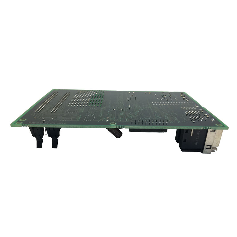
The FANUC A20B-2002-0031 is the servo amplifier control PCB for the FANUC Alpha series SVU1-40 and related drive configurations.
Within the A20B-2002 servo control board family, the -0031 variant steps up from the -0030 (which serves the smaller SVU1-12 and SVU1-20 models) to cover the higher-current SVU1-40 and SVU1-80 configurations — drives designed for larger Alpha series servo motors such as the α12/2000 and α22/2000.
This board sits at the intersection of digital control and high-power electronics. On one side, it receives digital servo commands from the CNC system and processes encoder feedback from the servo motor.
On the other side, it outputs gate drive signals that control the IPM (Intelligent Power Module) or IGBT transistors that ultimately switch the motor current. Everything that happens between the CNC's commanded position and the motor's actual torque output passes through the logic circuits on this PCB.
The SVU architecture that the A20B-2002-0031 supports is FANUC's standalone drive format — each SVU unit contains its own power rectifier, DC bus capacitor bank, and regenerative discharge circuit, making it fully self-contained.
This allows SVU units to be mounted remotely inside the machine structure, close to their respective servo motors, rather than requiring a centralised drive cabinet.
The A20B-2002-0031 control PCB enables this standalone operation by providing all of the control intelligence the drive needs to operate independently once powered and commanded by the CNC.
Key Specifications
| Parameter |
Value |
| Series |
A20B-2002 Alpha SVU control PCBs |
| Compatible Drives |
SVU1-40 (H104), SVU1-80 (H105), SVUC1-40 (H004) |
| Interface |
Type-B analogue PWM |
| Wiring Board Pair |
A20B-2002-0040, A20B-2002-0041 |
| Status |
Discontinued by manufacturer |
| Origin |
Japan |
Where the -0031 Fits in the A20B-2002 Control Board Sequence
FANUC's A20B-2002-003x series of control PCBs covers the complete Alpha SVU1 single-axis amplifier range through a logical progression matched to the drive's current rating:
- A20B-2002-0030: SVU1-12 (3A), SVU1-20
- A20B-2002-0031: SVU1-40, SVU1-80 (higher current rating)
- A20B-2002-0050: SVU1-130 (largest single-axis unit)
Each board revision (-0030, -0031, -0050) has slightly different component specifications tailored to the current levels of the drive it controls — specifically the current sense amplifier scaling, the gate drive current capability for the larger IPM modules in higher-current drives, and the overcurrent threshold settings stored in the firmware.
The -0031 cannot simply be substituted for the -0030 in a lower-power drive without risk of incorrect current scaling.
Type-B Interface — How the A20B-2002-0031 Receives Commands
The Type-B interface distinguishes this generation of FANUC servo amplifier from both the earlier Type-A analogue drives (which received ±10V velocity commands) and the later FSSB-based digital drives (which receive digital fibre-optic serial commands).
In Type-B operation, the CNC's axis control card outputs a PWM signal — a square wave at a fixed carrier frequency with duty cycle proportional to commanded velocity. The control PCB on the SVU demodulates this PWM signal to extract the velocity command, then drives the motor's current control loop based on this reference.
The Type-B interface is encountered in FANUC Series 0C, 15A/B, 16A/B, 18A, and 21TA CNC systems — a generation that spans most of the 1990s in machine tool manufacturing. Machines equipped with these CNC generations and Alpha SVU drives continue to operate in production environments worldwide, making the A20B-2002-0031 a relevant maintenance component despite its discontinued status.
Firmware and Motor Parameter Matching
The A20B-2002-0031 control PCB contains firmware that implements the servo motor control algorithm. Within this firmware, a set of motor parameters defines the control loop gains, the current limit, and the motor's electrical model (resistance, inductance, back-EMF constant). These parameters must match the specific servo motor connected to the drive.
FANUC loads these parameters into the drive during the factory configuration of the A06B-6089 drive unit.
When a replacement A20B-2002-0031 is installed, the motor parameters that were stored in the original board's firmware must be restored.
The SVU's front-panel parameter entry interface (accessed through the four pushbuttons: MODE, UP, DOWN, DATA SET) allows manual parameter entry by referencing the SVU maintenance manual (B-65195EN).
Alternatively, if the original PCB is physically damaged but the NV-RAM chip is intact, the chip can be transferred to the replacement board to preserve the original parameter set.
FAQ
Q1: How is the SVU1-40 (A06B-6089-H104) identified as using the A20B-2002-0031 rather than the -0030?
The drive's specification sheet and the FANUC Alpha series maintenance manual (B-65195EN) explicitly list the PCB specification for each SVU model. The H101 (SVU1-12) and H102 (SVU1-20) use the -0030 board.
The H104 (SVU1-40) uses the -0031 in combination with the -0040 wiring board.
The drive's nameplate confirms the order specification (A06B-6089-HXXX), which uniquely identifies the PCB contents. Never substitute a -0030 for a -0031 or vice versa without confirming current and parameter compatibility.
Q2: The SVU1-40 shows a DCSW alarm (regenerative discharge circuit failure). Is this likely a control PCB fault?
The DCSW alarm monitors the SVU's built-in regenerative discharge circuit. In the SVU1-40, which uses a separate external regenerative discharge unit (A06B-6089-H500 or similar) rather than a built-in resistor, the alarm may indicate: an open-circuit thermostat in the external resistor assembly, a failed connection in the thermostat monitoring circuit on the control PCB, or a genuinely overloaded regenerative resistor.
The control PCB is the reporting element but rarely the root cause of DCSW. Check the external discharge unit and its connection to the drive before suspecting the control board.
Q3: Can the A20B-2002-0031 from a working SVU1-80 be used to repair a failed SVU1-40?
The -0031 is the specified PCB for both the SVU1-40 (H104) and SVU1-80 (H105). However, the wiring board differs: H104 uses A20B-2002-0040 and H105 uses A20B-2002-0041.
If the control PCB alone is the failed component, and the wiring boards are different between the two drive models, a cross-model control board substitution requires verifying that the firmware parameter set stored in the PCB's NV-RAM is appropriate for the destination motor and drive configuration.
If the NV-RAM contains the correct parameters for the new drive's motor, the substitution is feasible.
Q4: What are the typical failure modes of the A20B-2002-0031 in long-service SVU drives?
The most common age-related failure is electrolytic capacitor degradation on the PCB's internal power supply rails — capacitors in the 10–100µF range on the control board's ±15V and +5V supply lose capacitance and increase ESR after 10–15 years of continuous operation.
This manifests as unstable or oscillatory servo behaviour before progressing to complete failure.
The second common mode is NV-RAM data corruption — the NV-RAM chip that stores motor parameters can fail, causing the drive to boot with incorrect or zero parameters, producing immediate servo alarms. ESD damage to the command signal receiver circuitry is the most common event-driven failure mode.
Q5: What information is needed before sending a failed A20B-2002-0031 to a repair centre?
Provide: the complete SVU drive order specification (A06B-6089-HXXX), the servo motor type connected to the drive (A06B-XXXX-BXXX from the motor nameplate), the CNC series and model (Series 0C, 16B, 18A, etc.), the alarm code(s) displayed on the SVU's LED indicator at the time of failure, and whether the failure was sudden (event-driven, such as after a collision or power surge) or gradual (increasing frequency of alarms over weeks or months).
This information allows the repair centre to replicate the fault condition and confirm the repair is fully effective before return.

 Your message must be between 20-3,000 characters!