FANUC A20B-2002-0033 | Alpha Series SVU2 Dual-Axis Servo Amplifier Control PCB — A06B-6089-H20x Series, Type-B PWM Interface, Discontinued CNC Legacy Spare, Japan Origin
Overview
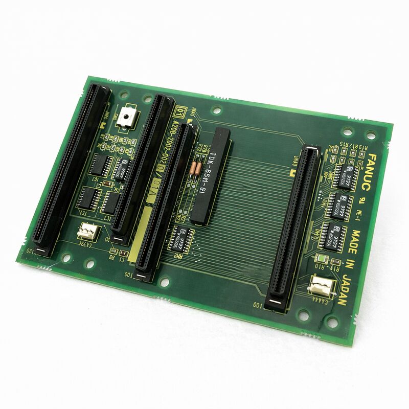
The FANUC A20B-2002-0033 is the control PCB for FANUC's Alpha series SVU2 dual-axis servo amplifier units. Where the SVU1 series (using the A20B-2002-0030 and -0031 control boards) drives a single servo motor axis per unit, the SVU2 drives two independent axes from a single physical enclosure — sharing one AC power input, one rectifier/DC bus assembly, and one set of control electronics, while maintaining fully independent servo control loops for each axis.
The A20B-2002-0033 is the board that makes this dual-axis intelligence possible.
This architecture is efficient in machines where two axes operate in close physical proximity or share similar mechanical environments.
A typical application would be the X and Z axes of a CNC lathe (both mounted within the machine's main casting), or the X and Y axes of a small machining centre, where running two separate SVU1 units would occupy twice the cabinet space and require twice the AC power wiring for no functional advantage.
The SVU2 combines both axes in a package that is more compact than two SVU1 units, with a shared power section that reduces cost and installation complexity.
The A20B-2002-0033 control board handles the logic for both axes — two independent sets of PWM demodulator circuits (one per axis), two servo control processors (or one processor timesharing between two axis control tasks), two sets of encoder feedback receivers, two gate drive output stages, and two independent alarm output lines.
Each axis's behaviour — speed, position, current limit, regenerative control, absolute encoder battery — is handled entirely by this one PCB, which explains both its complexity and its critical importance to the machine: a single board failure simultaneously disables both of the axes it controls.
Key Specifications
| Parameter |
Value |
| Function |
Dual-axis SVU2 servo amplifier control PCB |
| Compatible Drives |
A06B-6089-H201 to H210 (SVU2 series) |
| Interface |
Type-B analogue PWM (both axes) |
| Axes Controlled |
2 independent servo axes |
| Status |
Discontinued by manufacturer |
| Origin |
Japan |
SVU2 Drive Range — Understanding the H20x Model Codes
The SVU2 dual-axis units in the A06B-6089-H20x range are identified by two current ratings in the model designation, corresponding to the L-axis and M-axis current capabilities:
SVU2-12/12 (H201): 3A on both L and M axes — the smallest dual-axis configuration, suited to compact servo motors. SVU2-12/20 (H202): 3A on L, higher current on M — an asymmetric configuration for machines where one axis drives a heavier load. SVU2-20/20 (H203): Both axes at the next current tier — commonly found in mid-range lathe and machining centre axes.
SVU2-12/40 (H204), SVU2-20/40 (H205), SVU2-40/40 (H206): Progressive increase in M-axis or both-axis current rating — the H206 (40A/40A) is the highest-power symmetric dual-axis configuration in the SVU2 family.
SVU2-40/80 (H207) through SVU2-20/80 (H210): High-power M-axis variants for machines where one axis drives substantially larger servo motors.
The A20B-2002-0033 control PCB is specified for multiple variants across this range.
The wiring board that pairs with the control PCB varies by variant (A20B-2002-0060 through A20B-2002-0069), with each wiring board providing the current-sense scaling and power interface appropriate for the current rating of that drive model.
The A20B-2002-0033 control board itself handles the common control logic; the wiring board handles the current-level-specific analogue circuits.
Dual-Axis Simultaneous Control — How It Works
Running two servo axes from one control board requires careful attention to computational timing.
The control board's processor must complete both axis control loops — read L-axis encoder, compute L-axis error, compute L-axis current, output L-axis PWM, then repeat for M-axis — within the constraints of the PWM period.
At typical servo PWM frequencies (4–8kHz), the processor has 125–250µs per complete cycle to execute both loops.
FANUC's servo control architecture handles this through a combination of dedicated DSP (Digital Signal Processor) resources allocated to each axis's inner current loop, with the outer velocity and position loops executing at a lower rate that still satisfies the servo system's bandwidth requirements.
The apparent complexity is managed by FANUC's firmware, which the maintenance engineer only encounters when a firmware version mismatch causes unexpected servo behaviour during board replacement.
When a Dual-Axis Board Fails — Recognising the Symptom Pattern
Because the A20B-2002-0033 controls two axes, its failure pattern differs from a single-axis component failure.
The defining symptom of a control board failure on a dual-axis unit is the simultaneous appearance of servo alarms on both L and M axes — alarms that share the same timestamp and the same alarm code category.
Single-axis alarms (e.g., L-axis encoder error only, or M-axis overcurrent only, while the other axis operates normally) point to the motor, cable, encoder, or power stage of the affected axis — not to the shared control board.
The control board fails in a way that affects both axes simultaneously. If one axis is in alarm and the other is healthy, look first at the individual axis's hardware before suspecting the control board.
The exception to this rule is a firmware or NV-RAM failure on the control board that affects only one axis's parameter set — in this case, one axis may alarm on parameter-related codes while the other appears normal.
This failure mode typically presents as an axis that always alarms on startup with a parameter-type alarm code, even after a power cycle.
FAQ
Q1: If one axis of the SVU2 has failed and the other is working, does the whole drive need to be replaced?
Not necessarily. If the fault is in the control board (A20B-2002-0033), replacing the board restores both axes. If the fault is in one axis's power stage (IPM or IGBT, wiring board) while the control board and the other axis's power stage are healthy, board-level repair targeting only the failed power components is feasible.
SVU2 drives are routinely repaired at this level of disassembly by specialist FANUC repair centres.
However, if the drive is physically damaged (burned PCB traces, failed power module with carbonisation) the practical path is a complete drive exchange rather than component-level repair.
Q2: Can the A20B-2002-0033 parameters be reprogrammed if the NV-RAM data is lost?
Yes. The motor parameters are tabulated in the FANUC Alpha series maintenance manual (B-65195EN) for each motor type.
With the motor type number known from the motor nameplate, the complete parameter set for each axis (typically 20–40 parameters per axis) can be entered manually via the SVU2's front-panel buttons (MODE, UP, DOWN, DATA SET). The procedure is the same as for SVU1 units but must be performed twice — once for the L-axis parameter set and once for the M-axis parameter set.
The axis selection switch on the drive front panel alternates between L and M parameter entry modes.
Q3: Can an SVU1 control board (A20B-2002-0030 or -0031) substitute for the A20B-2002-0033 in a dual-axis unit?
No. The SVU1 control boards (-0030, -0031) have circuits and connector pinouts for one axis only. The SVU2 control board (-0033) has circuits and connectors for two independent axes — it is a physically and electrically different board.
Even if the connector spacing were similar, fitting an SVU1 board in an SVU2 drive would leave M-axis encoder feedback, M-axis gate drive, and M-axis alarm circuits unconnected. The result would be an immediate M-axis fault and potential hardware damage.
Only the correct SVU2 control board specification should be installed in SVU2 drives.
Q4: The SVU2 drive is showing alarm code 8 (IPM alarm) on both axes simultaneously. Does this confirm the control board has failed?
Not necessarily. IPM alarms on both axes simultaneously often indicate a power supply problem — DC bus undervoltage, a failed charging circuit, or an AC input phase loss — rather than a control board failure.
The control board's IPM monitoring circuit detects and reports the IPM's internally-generated protection signal; if the IPM itself is triggering protection due to undervoltage, both L and M axis IPMs will trigger simultaneously, generating the appearance of a dual-axis alarm.
Check AC input voltage (all three phases), DC bus voltage, and charging resistor condition before concluding the control board has failed.
Q5: What documentation should be gathered before a replacement A20B-2002-0033 is installed in a production machine?
Gather: both axis motor types from the motor nameplates (A06B-XXXX-BXXX), the complete parameter sets for both L and M axes read from the working drive (if the original drive is still partially functional), the SVU2 drive order specification (A06B-6089-HXXX), the CNC series and interface type (Series 0C, 16B, etc.), and the alarm codes that led to the board replacement.
If the drive's NV-RAM is intact (drive was working before a control board component failed), plan to transfer the NV-RAM chip to the replacement board to avoid manual parameter re-entry.

 Your message must be between 20-3,000 characters!