FANUC A20B-2002-0110 | 2-Slot Backplane PCB — A20B-2002 Series, CNC Controller Rack Interconnect, Power and Signal Distribution, Japan Origin
Overview
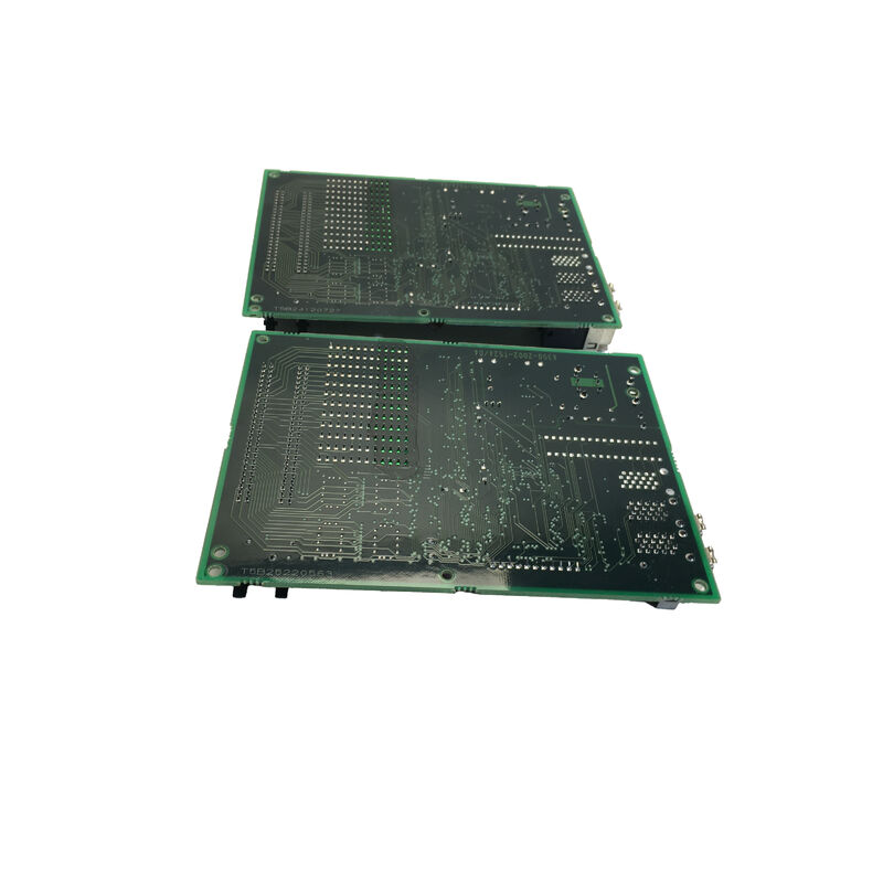
The FANUC A20B-2002-0110 is the 2-slot backplane PCB from FANUC's A20B-2002 series — the physical foundation on which two CNC control modules mount and operate together. In the engineering architecture of FANUC's Series 16/18 era CNC controllers, the control electronics are not built as a single monolithic board but as a collection of purpose-specific modules — main CPU, servo interface, I/O options, memory expansion, communication cards — that plug into a common backplane.
This modularity was a deliberate design choice: it allows failed modules to be replaced without disturbing working modules, enables system capability to be expanded by adding a new option card into an open slot, and simplifies manufacturing by allowing FANUC to mix and match modules to build different CNC configurations from a common hardware platform.
The backplane is what makes this work.
Every module in a FANUC controller rack plugs into the backplane through edge connectors — gold-plated contacts that mate with the card-edge fingers on each module's bottom edge. Through these connectors, the backplane delivers power supply voltages (the regulated DC rails from the CNC's power supply unit) to every module simultaneously, and provides the shared bus signal lines that allow modules to communicate with each other.
For a 2-slot backplane, two modules coexist in this shared electrical environment.
The A20B-2002-0110's 2-slot format makes it the most compact configuration in the series — used in controller sections where only two modules need to share a common rack, or in systems where individual rack sections are used to distribute the control electronics spatially within a large cabinet.
Larger FANUC rack configurations use 3-slot, 4-slot, or 6-slot backplane variants from the same A20B-2002 family; each handles the same fundamental function but with more module positions.
Key Specifications
| Parameter |
Value |
| Function |
2-slot passive backplane PCB |
| Type |
Passive — no active components |
| Module Slots |
2 positions |
| Series |
A20B-2002 |
| Rack Role |
Power + bus + signal interconnect |
| Origin |
Japan |
The Engineering Inside a "Passive" Backplane
Calling the A20B-2002-0110 a "passive" board means it contains no microprocessors, no memory, and no active signal processing. But passive does not mean simple.
The PCB design of an industrial backplane involves several engineering challenges that are invisible from the outside:
Power trace design: The backplane's power rails carry the combined load of all modules installed simultaneously.
For a 2-slot backplane in a FANUC CNC system, this means the copper traces carrying +5V, ±15V, and +24V must handle the peak current draw of two fully loaded control modules — potentially several amps — without excessive resistive voltage drop, and without traces heating to the point of PCB substrate damage.
The trace width, copper weight, and via design all contribute to the board's long-term power delivery integrity.
Bus signal integrity: The parallel data bus traces on the backplane carry digital signals at speeds up to several tens of megahertz.
At these frequencies, the PCB trace acts as a transmission line — its impedance must match the driving and receiving circuits' impedance to prevent signal reflections that cause bus errors.
The backplane's layer stack, trace geometry, and termination design are all engineered for signal integrity at the specified operating frequency.
Isolation between modules: Despite the shared bus, some signals on the backplane must be routed only to specific slots.
The backplane's artwork defines exactly which connector pins are common across all slots and which are dedicated to individual slots — an error in this routing at PCB design time would cause two modules to interfere with each other's dedicated signals.
FANUC's backplane designs are validated against the full range of module combinations that can be installed.
When the A20B-2002-0110 Needs Replacement
Backplane failures are infrequent — the board has no moving parts and no active components that age and fail under normal electrical stress. When they do occur, the causes are specific:
Surge damage: A voltage spike on the AC supply or the CNC's internal DC bus, if severe enough to exceed the PCB substrate's dielectric strength, causes insulation breakdown between adjacent power and ground traces.
The damaged area appears visually as carbonised or discoloured PCB material — tracking — and represents an ongoing partial short circuit that may arc under load or worsen progressively.
Any board showing visible tracking from a surge event should be replaced, not continued in service.
Coolant or contamination ingress: Machine tool environments produce airborne coolant mist, metallic dust, and oil aerosols. Over years of operation, this contamination enters the control cabinet and settles on PCB surfaces.
On a backplane, where power and ground planes run in close proximity on the same board, a conductive contamination film creates leakage paths that cause intermittent bus faults or power rail instability.
Cleaning the board with appropriate electronics-grade solvent may resolve the problem temporarily; if contamination re-accumulates, board replacement becomes necessary.
Physical connector damage: Repeated insertions and removals of modules — over many years of maintenance — gradually wear the backplane's edge connector contacts. Worn or oxidised contacts produce intermittent module faults that are indistinguishable at the system level from a faulty module.
Visual inspection of the connector contacts and continuity testing of the connector pins identifies this failure mode.
FAQ
Q1: How is the A20B-2002-0110 identified as the correct 2-slot backplane for a specific CNC system?
The correct backplane is specified in the CNC's maintenance manual or hardware connection manual — FANUC publishes hardware configuration tables that list which backplane part number is used with which combination of modules.
The installed board's part number label (typically on one edge of the PCB) also directly confirms the installed variant.
Within the A20B-2002 family, 2-slot variants differ from 3-slot or 6-slot variants in physical dimensions, slot count, and sometimes connector pinout — always match the exact part number from the original installation.
Q2: Do all modules from the A20B-2002 series plug into the A20B-2002-0110 backplane?
Not necessarily — module-to-backplane compatibility depends on matching the board's connector pinout and slot assignments to the module's interface requirements.
FANUC's hardware documentation specifies which modules are compatible with which backplane variants.
Some modules are slot-specific (designed for a particular slot position) and cannot be installed in an arbitrary slot.
Before installing any module into a replacement backplane, verify the slot assignments against the CNC's hardware manual.
Q3: Can the CNC continue operating if the backplane develops an intermittent fault, provided it clears on power cycle?
Operating a CNC system with a known-suspect backplane carries real production risk. Intermittent backplane faults that clear on power cycle indicate a marginal contact or a partial contamination short that is near the threshold of causing a persistent fault.
The condition will worsen — power cycling is not a maintenance strategy, it is a symptom that maintenance is overdue.
The appropriate response is to schedule board inspection and replacement at the earliest maintenance window, keeping a spare backplane on hand to minimise the duration of the planned downtime.
Q4: Is the A20B-2002-0110 the same as the A20B-2002-0020 (3-slot backplane for Series 16/18)?
No — the -0020 is a 3-slot backplane and the -0110 is a 2-slot backplane. They are different boards with different physical dimensions and different slot counts.
They cannot substitute for each other; the mounting points, connector positions, and board outline dimensions are matched to specific rack frames.
Confirm the slot count and the exact part number of the original board before ordering a replacement.
Q5: What precautions are essential when removing and reinstalling modules during a backplane replacement?
Power down completely before starting. Document the position of every module before removal — photograph the rack from both front and back. Remove modules with firm, even pressure along their length — rocking a module during removal damages both the module's card-edge fingers and the backplane's connector contacts.
With the backplane replaced, install each module in its documented original slot position and confirm it is fully seated before applying power.
On first power-up, verify all modules initialise normally through the CNC's diagnostic screens before returning the machine to production.

 Your message must be between 20-3,000 characters!