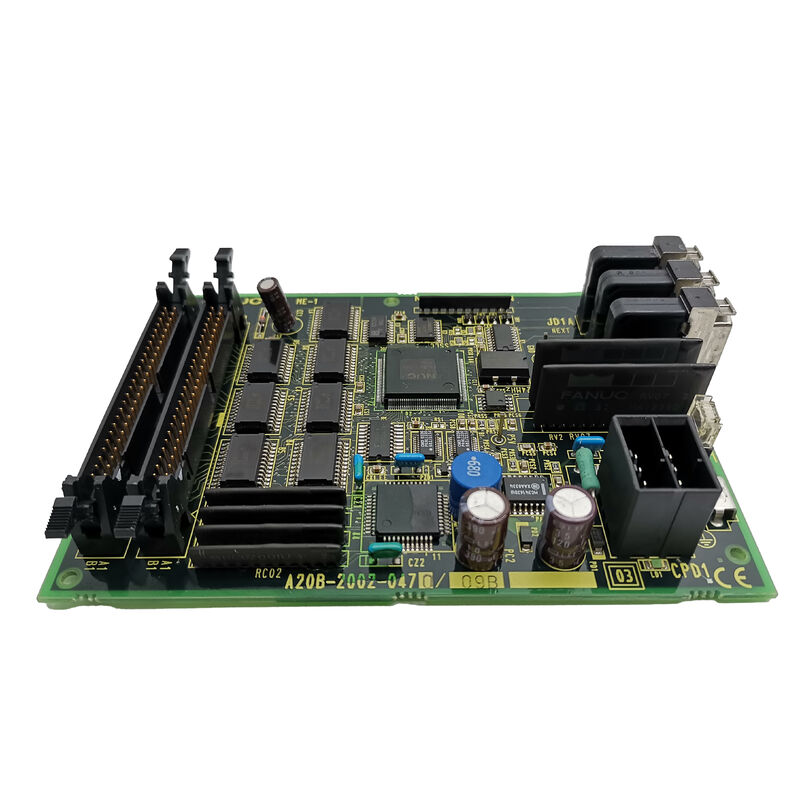
FANUC A20B-2002-0270 | CNC Control PCB — A20B-2002 Series, Industrial Automation Spare, Japan Origin
Overview
The FANUC A20B-2002-0270 is a control PCB within one of FANUC's busiest board families — the A20B-2002 series. This family spans a wide range of functions in the CNC control rack. Some variants serve as backplane structures. Others handle I/O interface, signal routing, or communication bridging.
What they share is a common place in the control unit's architecture: they sit between the high-level CPU logic and the machine's physical I/O, keeping signals clean, timing correct, and data paths intact.
FANUC's modular design philosophy is on full display in the A20B-2002 family.
Rather than packing all functions onto a single board, the control unit distributes work across dedicated boards. Each board does one job well. This makes maintenance predictable — a fault in one module can be isolated and replaced without disturbing the rest of the system.
The A20B-2002-0270 operates within this architecture as a module within the control rack.
It connects into the system via its edge connectors and operates continuously during machine operation. Industrial-grade components are used throughout. The board is designed for the demanding thermal and electrical environment of a production machine tool — not a laboratory instrument.
Key Specifications
| Parameter |
Value |
| Series |
A20B-2002 |
| Function |
CNC control circuit board |
| Compatible CNC Families |
FANUC Series 16, 18, 20, 21 and compatible |
| Operating Environment |
Industrial CNC control rack |
| Power Supply |
System-supplied internal voltage |
| Construction |
FR-4 PCB substrate, SMD components |
| Status |
Available — refurbished, tested |
| Origin |
Japan |
The A20B-2002 Family in FANUC Control Architecture
FANUC's control unit architecture is deliberately modular. The A20B-2002 series sits in the middle of this structure. At the top sits the main CPU board — the system's decision-maker. At the bottom sit the I/O modules, servo drives, and spindle amplifiers.
In between, the A20B-2002 boards handle the infrastructure: routing signals, managing bus timing, distributing power within the rack, and providing the connectors that cables plug into.
This layered design has real maintenance advantages.
When a fault develops, the physical boundary between boards helps isolate where the problem lies. A fault in the A20B-2002-0270 typically produces symptoms that are clearly different from a main CPU failure or a servo drive failure.
Signal-level faults — intermittent data errors, incorrect I/O states, unexpected alarm codes — often trace to this level of the architecture.
Boards in this family do not store machine-specific data. Parameters, programmes, and tool offsets live on the main CPU board's memory modules.
Replacing an A20B-2002-0270 does not require a full parameter reload.
Verify the system starts and all I/O functions respond correctly after replacement. That is usually sufficient to confirm the repair.
Condition and Testing
Refurbished A20B-2002-0270 boards available on the market should have undergone testing on a FANUC-compatible test setup before shipping.
Key checks during refurbishment include:
- Inspection of all connector pins for damage or corrosion
- Verification of power supply rail integrity across the board
- Functional test confirming signal routing and bus communication operate correctly
- Visual inspection for physical damage, burnt traces, or component failure
Boards shipped without documented testing should be treated with caution.
An apparently functional board that fails intermittently is harder to diagnose than one that fails immediately — intermittent faults waste more time than immediate failures.
FAQ
Q1: How do I confirm the A20B-2002-0270 is the failed board before ordering a replacement?
Fault isolation within the A20B-2002 layer requires systematic signal tracing. If the CNC generates alarm codes that indicate I/O communication errors, bus faults, or specific signal failures, cross-reference the alarm codes in the FANUC maintenance manual against the board's documented connector assignments.
If the alarm points to a function handled by this board and all other possible causes (cables, connectors, adjacent boards) have been eliminated, the A20B-2002-0270 is the most likely candidate.
Q2: Does replacing the A20B-2002-0270 require any parameter settings to be changed?
No. Boards in the A20B-2002 series do not store machine-specific parameters or configuration data. Parameter data resides in the FROM/SRAM modules on the main CPU board. After replacing the A20B-2002-0270, power up the CNC normally and verify system function.
No parameter entry is required unless an alarm code specifically indicates a parameter issue unrelated to the board swap.
Q3: The CNC was producing intermittent alarms for weeks before shutting down completely. Could the A20B-2002-0270 be the cause?
Intermittent alarms followed by permanent failure is a common pattern for failing PCBs.
Thermal cycling causes solder joints to develop micro-cracks that open when hot and close when cold. The same applies to electrolytic capacitors that degrade gradually, producing erratic behavior before failing.
If the intermittent alarms pointed to I/O or signal-level faults and the CNC eventually stopped with a definitive error in that same area, the A20B-2002-0270 is a reasonable suspect.
Q4: Are there multiple sub-variants of A20B-2002-0270 (e.g., /01A, /02A suffixes)?
FANUC sometimes uses sub-variant suffixes to indicate minor hardware revisions.
A board with a suffix may have updated components compared to the base version but performs the same function. In most cases, a board with a different minor suffix is a direct replacement.
Confirm with the parts supplier if the board being purchased carries a different suffix from the original — they can advise whether functional compatibility is maintained.
Q5: What precautions should be taken when handling the A20B-2002-0270 during installation?
Always power down the CNC completely and wait for the DC bus capacitors to discharge before accessing the control rack. Ground yourself with an ESD wrist strap before touching the board. Handle only by the edges — avoid touching component surfaces.
Align connectors carefully before seating — forcing a misaligned board can bend pins.
After installation, verify all cables are correctly reconnected before powering up. Keep the original board in antistatic packaging until the replacement is confirmed working.

 Your message must be between 20-3,000 characters!