A20B-2002-0321 | FANUC Drive and Servo PCB — A20B-2002 Series / 032x CNC Servo Drive Board
A20B-2002 — FANUC CNC and Servo Drive Board Series
The A20B-2002 series is a broad FANUC board family confirmed across CNC main CPU boards, servo drive PCBs, and auxiliary control boards spanning multiple CNC and drive generations. Within this series:
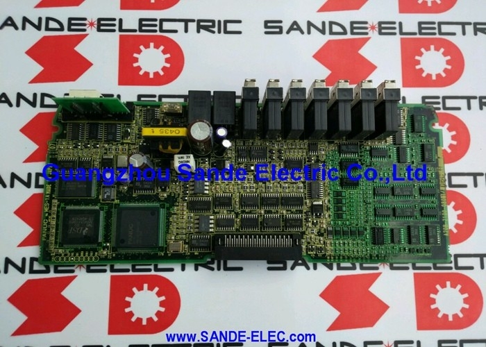
The A20B-2002-0321 is explicitly described as a "DRIVE/SERVO PC BOARD" — a dedicated servo drive PCB handling servo motor control functions within the FANUC drive architecture.
Servo drive PCBs in the A20B-2002 series serve defined functions within servo amplifier modules and CNC drive systems:
Velocity and current loop execution: Processing velocity commands from the CNC and computing the required motor current commands to achieve the commanded speed and position.
Drive protection: Monitoring servo drive operating conditions — current levels, temperature, DC bus voltage — and generating fault responses to protect the power electronics.
Interface and signal routing: Providing the signal paths between the CNC's servo interface and the drive's power stage components.
Key Product Information
| Parameter |
Value |
| Part Number |
A20B-2002-0321 |
| Series |
A20B-2002 |
| Range |
032x |
| Type |
Drive / Servo PCB |
| Application |
FANUC CNC servo drive |
Application Scenarios
Servo drive PCB fault: A FANUC servo drive system develops a control-level fault traceable to the A20B-2002-0321. The board is identified from its part number label. Replacement restores drive control function.
CNC drive maintenance: A production facility maintaining FANUC CNC servo drive equipment replaces A20B-2002-0321 as part of scheduled drive board maintenance.
FAQ
Q1: How do I confirm A20B-2002-0321 is the correct servo PCB for my FANUC drive system?
Read the part number from the installed board's label inside the servo drive unit. If it reads A20B-2002-0321, this is the confirmed replacement. Cross-reference with the applicable FANUC servo drive maintenance manual's board assignment and spare parts tables.
Q2: What types of servo fault indicate an A20B-2002-0321 PCB failure?
Servo drive PCB faults typically produce control-level alarms — velocity loop errors, current feedback anomalies, or protection faults that persist despite healthy IGBT transistors and motor encoder. If the power stage and motor test as healthy but the drive continues to fault on enabling, the servo PCB is the next diagnostic focus. Check the CNC's servo alarm display for the specific alarm code.
Q3: Does replacing A20B-2002-0321 require servo parameter re-entry?
Servo parameters reside in the CNC's main parameter memory — not in the servo drive PCB. Replacing A20B-2002-0321 does not affect stored servo parameters. After fitting the replacement board, the CNC downloads servo parameters to the drive during power-on initialisation. Verify correct servo response at low speed before returning to production.
Q4: What ESD precautions apply when handling A20B-2002-0321?
Handle with a grounded anti-static wrist strap on an ESD-safe surface. Store in anti-static packaging. Power down the servo drive system completely and verify the DC bus has discharged before accessing internal boards — servo drive DC bus voltages are hazardous and persist after mains power removal.

 Your message must be between 20-3,000 characters!