FANUC A20B-2003-0750 | Operator Panel I/O PCB (B1) — A20B-2003 Series, CNC Machine Tool Operator Interface Control Board, Japan Origin
Overview
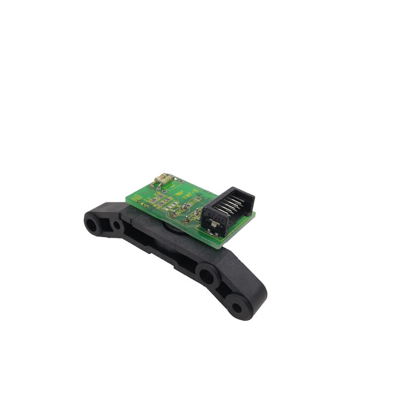
The FANUC A20B-2003-0750 is the Operator Panel I/O PCB (B1 designation) — the electronics board behind the physical surface of the CNC machine's operator panel. Every button the operator presses, every indicator lamp that lights up, every position of the feed rate override dial, and the machine's emergency stop circuit all route through this board. It is, in practical terms, the sensory and motor nervous system of the operator-machine interface.
In FANUC's CNC architecture, the operator panel is not simply a passive switch and lamp assembly wired directly to the CNC's I/O modules. The operator panel I/O board adds a layer of intelligence and signal conditioning between the raw mechanical switches and the CNC's internal logic.
Raw switch closures are debounced and filtered to prevent contact bounce from generating spurious inputs. Lamp drive currents are regulated to prevent LED or incandescent backlight degradation from voltage transients.
The MPG (Manual Pulse Generator) handwheel signals are received and conditioned into pulse trains for the CNC's manual operation mode.
The emergency stop circuit is implemented with the appropriate safety logic to ensure that the E-stop remains effective regardless of CNC software state.
The "B1" designation in the board's official description identifies a specific configuration within the A20B-2003-0750 product — operator panel I/O boards in the A20B-2003 series are produced in variants (B1, B2, etc.) that correspond to different operator panel configurations with different numbers of I/O points, different MPG interface options, and different connector layouts to match the specific operator panel the board is fitted to.
Key Specifications
| Parameter |
Value |
| Function |
Operator Panel I/O PCB (B1) |
| Series |
A20B-2003 |
| Interface |
I/O Link / direct operator panel bus |
| I/O Functions |
Pushbuttons, lamps, MPG, E-stop, overrides |
| Origin |
Japan |
What the Operator Panel I/O PCB Actually Does
The scope of functions managed by the A20B-2003-0750 reflects everything that happens at the operator's physical interaction point with the machine. Starting from the panel's input side:
Pushbutton and key switch inputs: Each pushbutton and key switch position on the operator panel is wired to an input circuit on the A20B-2003-0750.
When a button is pressed, the board's input circuit registers the contact closure, debounces it (filtering out the brief oscillation of the mechanical contact before it settles), and reports the logical state to the CNC's PMC. The PMC then acts on the button press — starting the cycle, activating coolant, selecting a programme, etc.
Manual Pulse Generator (MPG) interface: The handwheel, or MPG, generates pulse trains (typically 100 pulses per revolution) as the operator rotates it. The A20B-2003-0750 receives these pulses and conditions them for the CNC's manual pulse input. The MPG signal path requires careful electrical treatment — the signals are differential, the pulse count must be precise with no missed or phantom pulses, and the direction (CW vs CCW) must be correctly decoded.
Any fault in the MPG interface circuit on this board directly impairs the operator's ability to jog axes manually.
Override switches: Feed rate override, spindle override, and rapid override dials produce variable-position signals — either a multi-position rotary switch (generating a binary code) or an analogue pot — that the board decodes into percentage override values reported to the CNC.
Indicator lamp outputs: The CNC's PMC drives output signals to activate indicator lamps on the panel.
The board's output driver circuits provide regulated current to each lamp, protecting the PMC's I/O from direct lamp loading and providing the correct current for both LED and incandescent indicator types.
Emergency stop (E-stop) circuit: The E-stop button connects through a redundant safety circuit on the board, ensuring the E-stop signal reaches both the CNC's servo control and the machine's safety relay in parallel — the board's implementation must satisfy the relevant safety standards for the E-stop function.
Failure Symptoms That Indicate an A20B-2003-0750 Problem
Operator panel I/O boards fail in ways that are immediately visible to anyone standing at the machine's control console:
Unresponsive buttons: One or multiple panel buttons fail to produce any CNC response, even though the PMC diagnose screen confirms the CNC is in the correct mode to accept those inputs.
This suggests an input circuit failure on the board — either a failed input buffer IC or a damaged connector pin.
Phantom button presses: The CNC responds to a function command without the operator pressing the corresponding button.
This suggests an input circuit stuck in the closed state — possibly a failed pull-up resistor or a damaged input IC with a leaking output.
Lamp anomalies: Panel indicator lamps that are permanently lit, permanently off, or flickering when they should be steady — not caused by PMC logic, but by failed lamp driver ICs or open-circuit output traces on the board.
MPG dysfunction: The handwheel rotates but axis movement is erratic, inconsistent, or absent. The MPG pulse train is missing or corrupted at the board level.
E-stop circuit fault: The CNC generates an E-stop alarm that cannot be cleared even when the physical E-stop button is released.
This requires immediate investigation as an E-stop circuit fault can represent both a safety and operational issue.
FAQ
Q1: How is a failed A20B-2003-0750 distinguished from a failed PMC output or input signal in the CNC itself?
The diagnosis path is: first check the PMC diagnose screen (G/F address inputs and outputs). If the PMC diagnose screen shows that an input signal is stuck active or inactive regardless of the physical button state, the issue is on the I/O path between the button and the PMC — which includes the A20B-2003-0750.
If the PMC diagnose screen shows the input correctly following the physical button, but the machine's function fails to activate, the issue is in the PMC ladder or the output circuit. I/O board faults typically show inputs that do not follow physical panel state.
Q2: Can the A20B-2003-0750 be replaced without backing up CNC parameters or programmes?
Yes. The operator panel I/O board stores no CNC programme or parameter data. It is a pure signal interface device — no SRAM, no battery, no programmable memory. Replacing it requires only power-down, physical board swap, and power-up.
The CNC's parameters, programmes, and PMC ladder are unaffected by operator panel board replacement.
The only post-replacement verification needed is functional testing of all panel buttons, lamps, MPG, and E-stop to confirm the replacement board is correctly wired and functional.
Q3: The MPG handwheel is unresponsive after the A20B-2003-0750 was replaced. What should be checked first?
First confirm the MPG cable is correctly reconnected to the new board — MPG cables are sometimes multi-connector assemblies where one connector is easily missed. Second, confirm the axis selection switch on the operator panel is correctly set to an active axis.
Third, check the CNC's parameter settings for MPG magnification and axis selection if the MPG was functional before the board replacement — these settings are in the CNC and are not affected by the board change, but confirming them eliminates them as variables.
Finally, verify the MPG unit itself is functional by measuring its output signals with an oscilloscope as the handwheel is rotated.
Q4: Is the A20B-2003-0750 the same for all machine tool builders, or is there a machine-specific version?
The A20B-2003-0750 (B1 configuration) is FANUC's standard operator panel I/O board for a defined panel configuration. Machine tool builders who use this standard FANUC operator panel assembly will use this board.
However, machine tool builders who design their own custom operator panels — with different numbers of buttons, non-standard MPG interfaces, or proprietary lamp layouts — may use a different I/O board model or a custom interface between their panel and the standard FANUC I/O board.
Before ordering a replacement, confirm against the machine's electrical schematic or the existing board's label that the A20B-2003-0750 is the correct board for the specific machine's panel configuration.
Q5: What are the most common causes of A20B-2003-0750 failure in long-service machines?
Contamination is the leading cause in machine tool environments — coolant mist, oil aerosol, and metallic dust ingress through the operator panel's ventilation slots over years of operation deposits conductive films on the board surface, causing short circuits between adjacent tracks or input pins.
The second most common cause is contact-related degradation of the board's connector sockets — years of operator panel opening for maintenance gradually works the card-edge or mating connectors loose, causing intermittent contact that presents as random button failures.
The third cause is lamp driver IC failure from overcurrent if a panel lamp is replaced with an incorrect type that draws more current than the driver IC's rating.

 Your message must be between 20-3,000 characters!