A20B-2100-0762 | FANUC Alpha-i Servo PSM Control Board — Power Shutoff / Servo DC Bus Supply PCB / Replaced by A20B-2101-0392
What the PSM Does — and Why Its Control Board Matters
In a FANUC Alpha-i servo system, the PSM (Power Supply Module) occupies the leftmost position in the drive cabinet. Every SVM (servo amplifier module) and SPM (spindle amplifier module) in the system draws its operating power from the PSM — the PSM converts the incoming AC mains supply into the regulated DC bus voltage that the amplifier modules use to drive motors.
The PSM is not a passive transformer. It contains active rectification and regeneration circuitry, intelligent monitoring of the DC bus voltage, and a power shutoff mechanism that interrupts the DC bus when the system is commanded to stop or when a fault is detected. All of this intelligence is controlled by the PCB inside the PSM.
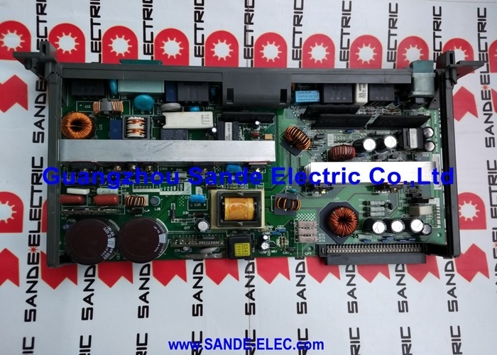
The A20B-2100-0762 is this control board — the electronic core of the Alpha-i PSM. It manages the DC bus voltage regulation, monitors the PSM's internal temperature and operational status, and executes the power shutoff sequence when required.
Key Product Information
| Parameter |
Value |
| Board Function |
PSM control board with power shutoff |
| Module Series |
FANUC Alpha-i |
| Module Type |
PSM (Servo Power Supply Module) |
| Replacement |
A20B-2101-0392 |
| Application |
CNC servo system DC bus supply |
Power Shutoff Function — Safety and Controlled Stop
The power shutoff function built into the A20B-2100-0762-equipped PSM provides controlled termination of the DC bus supply to all amplifier modules. When the CNC commands a shutdown — either through normal programme completion, operator stop, or emergency stop — the PSM's power shutoff circuit responds by safely discharging and interrupting the DC bus.
Without a controlled shutoff, residual charge in the DC bus capacitors continues supplying the amplifiers after stop command, creating a safety hazard and delaying the system's ability to restart. The power shutoff function ensures the DC bus reaches a safe voltage within a defined timeframe after the stop command, making the system predictable for both safety and restart sequencing.
When the A20B-2100-0762 fails, the PSM may lose the ability to correctly sequence the power shutoff — resulting in PSM alarms, failure to enable the DC bus on startup, or erratic bus voltage behaviour.
Application Scenarios
PSM control board failure: A FANUC Alpha-i drive system fails to establish DC bus voltage after power-on. The PSM displays an alarm and does not progress past the initial self-check. After confirming the AC input and the DC bus circuit are intact, the A20B-2100-0762 control board is identified as the fault. Replacement — or fitting the A20B-2101-0392 — restores the PSM to normal operation.
PSM power shutoff fault: The drive system fails to execute a controlled stop — the DC bus does not shut down correctly on E-stop command. Diagnosis traces the fault to the power shutoff circuit on the A20B-2100-0762. Replacing the board restores the correct shutdown sequence.
FAQ
Q1: What is the difference between the A20B-2100-0762 and the A20B-2101-0392?
The A20B-2101-0392 is the updated replacement for the A20B-2100-0762. The replacement board serves the 6110 and 6120 HV series Alpha-i PSM units at 400–480V AC. The -0762 and -0392 share the same functional role (PSM control board with power shutoff) but the -0392 reflects hardware updates in FANUC's Alpha-i PSM product evolution. Confirm PSM model compatibility before fitting the replacement.
Q2: Can the PSM operate without the DC bus connected to any servo amplifiers?
The PSM can establish and hold the DC bus voltage without amplifiers connected. This is useful for testing the PSM in isolation. However, the PSM's normal operating state is with amplifiers on the DC bus — the system monitors bus loading and responds to amplifier status signals. Operating the PSM for extended periods without connected amplifiers is not a standard operating condition and may trigger protection alarms depending on the PSM configuration.
Q3: What alarm codes indicate the A20B-2100-0762 control board has failed?
FANUC Alpha-i PSM alarms are displayed on the PSM's status LED or communicated to the CNC as SV alarm codes. PSM-specific alarms — including DC bus undervoltage, DC link overcharge, power shutoff circuit fault, and PSM main circuit alarm — are candidates for a control board fault. Single-axis servo alarms or motor-specific alarms typically point to the servo amplifier modules rather than the PSM.
Q4: Does the PSM require any parameter settings after the A20B-2100-0762 is replaced?
The PSM control board does not carry CNC servo parameters — these remain in the CNC's main parameter memory. However, the PSM may store internal hardware configuration or calibration data. After fitting a replacement board, power up the system and observe whether the PSM completes its self-check and establishes DC bus voltage normally. If configuration alarms appear, consult the Alpha-i servo amplifier maintenance manual for any post-replacement verification steps.
Q5: Is it safe to work inside the PSM with the unit powered down?
No — not immediately after power-down. The PSM's DC bus capacitors retain a dangerous voltage charge after AC mains power is removed. Wait for the discharge interval specified in the FANUC Alpha-i servo amplifier maintenance manual (typically 20–30 minutes, or until the charge LED indicator shows the capacitors have discharged) before opening the PSM housing or handling any internal components including the A20B-2100-0762 board.

 Your message must be between 20-3,000 characters!