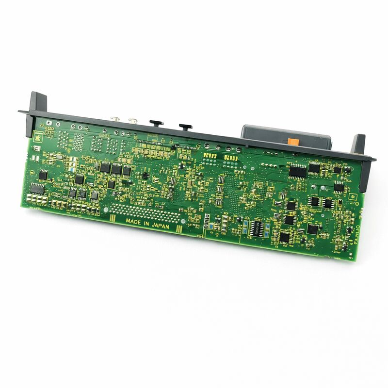
FANUC A20B-2101-0890 | Single-Axis Servo Control Board — A20B-2101 Series, CNC Servo Drive, Japan Origin
Part Number: A20B-2101-0890
Manufacturer: FANUC Corporation (Japan)
Product Type: Servo Control Board (PCB)
Board Series: A20B-2101
Application: FANUC CNC servo drive system — single-axis control
Product Type: Printed Circuit Board (PCB)
Overview
The A20B-2101-0890 is a single-axis servo control printed circuit board from FANUC's A20B-2101 series. The A20B-2101 series covers servo drive control boards used within FANUC's servo amplifier units — the boards that manage the intelligence of the servo drive, handling the position and velocity loop processing, current control, protection logic, and amplifier communication for a single servo axis.
These boards are the control electronics that make a servo amplifier behave like a servo amplifier rather than just a power inverter.
The power section of a servo amplifier converts the DC bus voltage into variable-frequency AC to drive the motor.
The control board — the A20B-2101-0890 — determines exactly how that power is applied: at what current level, at what timing, and in response to what feedback. Without the correct control board, the power section is inoperable.
The A20B-2101 series boards serve FANUC's range of servo amplifier module designs. These amplifiers — found in FANUC's αi, α, and related series drive systems — are the units that power the servo motors in CNC machine tools.
Each axis in the machine has its own amplifier. Each amplifier contains a control board. When a control board fails, that axis stops.
The A20B-2101-0890 is the replacement board that restores that axis.
Key Specifications
| Parameter |
Value |
| Part Number |
A20B-2101-0890 |
| Manufacturer |
FANUC Corporation |
| Product Type |
Servo Control Board (PCB) |
| Board Series |
A20B-2101 |
| Axis Count |
1 (single-axis) |
| Application |
FANUC CNC servo amplifier control section |
| Origin |
Japan |
| Operating Temperature |
0 – 55°C (as installed in amplifier) |
| Storage Temperature |
−20 – 55°C |
| Humidity |
75% RH max (non-condensing) |
| Condition Available |
New (surplus) / Refurbished / Repaired |
The Servo Drive Control Board — Core Functions
A servo drive control board handles several distinct but interrelated functions simultaneously. Understanding these functions clarifies what the A20B-2101-0890 does and what happens when it fails.
The current loop is the innermost control loop. It compares the commanded motor current to the actual motor current (measured by the amplifier's current sensors) and adjusts the PWM output to bring actual current to the commanded level. This loop runs at a high update rate — typically in the tens of kilohertz range — to respond quickly to current disturbances.
The velocity loop runs outside the current loop. It compares the commanded velocity to the actual velocity (derived from the encoder feedback) and produces a current command. The velocity loop closes around the current loop.
The position loop runs outside the velocity loop. The CNC's interpolator produces position targets.
The servo drive's position loop compares these targets to the actual encoder position and generates velocity commands.
All three loops run on the control board's DSP or processor.
The board also runs the amplifier's protection logic: monitoring the IGBT temperatures, the DC bus voltage, the motor current limits, and any overcurrent or overvoltage events.
When a fault is detected, the control board issues the alarm and shuts down the output.
A20B-2101 Series — Servo Amplifier Board Family
The A20B-2101 series is a substantial family covering servo drive control boards for multiple FANUC amplifier product lines. Within this family, different variants serve different drive current ratings and motor configurations.
The -0890 variant provides the control function for its specific drive configuration.
A single-axis designation means this board controls one servo axis within one amplifier module.
FANUC produces both single-axis (SVM1) and multi-axis (SVM2, SVM3) servo amplifier modules.
Single-axis modules are used where only one motor is driven by that amplifier position.
The A20B-2101-0890 serves the control section of one of these single-axis amplifier configurations.
Fault Diagnosis — Is It the Control Board?
When a single servo axis produces a fault alarm, the control board is one of several possible fault locations.
Others include the motor, the encoder, the power transistors (IGBTs) in the amplifier, and the motor cables and connectors.
Control board faults have a characteristic pattern: the alarm codes typically relate to the control section's own self-diagnostics — communication errors, processing faults, internal reference voltage failures — rather than the power stage monitoring (overcurrent, overvoltage). Power stage faults tend to produce overcurrent or overtemperature alarms; control board faults tend to produce CNC communication or drive ready alarms.
If a servo axis produces a drive ready (VRDY) alarm immediately at power-on — before any motion is commanded — with no other apparent cause, the control board is a strong candidate. The control board runs self-diagnostics at power-on.
A failure in this sequence produces an immediate alarm that persists regardless of the axis state.
FAQ
Q1: One servo axis shows a persistent "drive not ready" alarm immediately at power-on. Other axes initialize normally. The motor and encoder test as good. Is this the A20B-2101-0890?
A drive not ready alarm at power-on, before motion is commanded and with the motor and encoder confirmed good, is consistent with a control board fault.
The control board's power-on self-test has likely failed. The board issues the alarm rather than declaring itself ready.
This is distinct from a power stage fault, which typically produces overcurrent or temperature alarms under load. Board replacement is the appropriate diagnostic step.
Q2: The servo drive was working and then produced a position error alarm during cutting. It has since refused to initialize. Could this be the control board?
A drive that fails mid-cycle and then refuses to re-initialize may have experienced a fault that damaged the control board — an overcurrent event, an overvoltage transient, or a thermal event.
The power-stage protection components may have absorbed the initial event, but the control board's processing or communication circuits may have been damaged by the energy that reached them before the protection responded.
Inspect the control board for visible damage and replace it if no damage is visible on the power transistors.
Q3: After control board replacement, the drive initializes but the axis runs rough at low speed. The servo tuning parameters were restored. What else should be checked?
Rough running at low speed with correct parameters points to the current loop.
The control board's current measurement circuits may have a calibration offset compared to the previous board, or the amplifier's current sensor characteristics may require the current loop gains to be re-verified.
Also check the encoder feedback — damaged encoder cables can produce rough motion even when the drive initializes correctly.
Q4: Can the A20B-2101-0890 be repaired at component level, or is full board replacement the only option?
Some faults on servo control boards are component-level repairable — blown fuses, damaged protection devices, failed signal conditioning components.
Faults in proprietary FANUC processor ICs or custom gate drive ASICs are generally not repairable because these parts are not independently available.
A qualified FANUC drive repair specialist can assess the specific failure mode and determine whether component repair is viable for a particular fault.
Q5: How should this board be stored as a preventive spare?
Store in anti-static packaging. Keep at stable room temperature, away from humidity and temperature extremes.
If the board carries any user-configurable settings (switches or jumpers), record these settings from the installed board before purchasing a spare — this makes installation faster when the spare is needed.
Inspect connector contacts annually during storage. Replace the packaging if it becomes damaged.
A board stored correctly retains its condition indefinitely.

 Your message must be between 20-3,000 characters!