A20B-2101-0922 | FANUC A20B-2101 Series Servo Drive Circuit Board — CNC / Robot Servo Amplifier Replacement PCB
A20B-2101 Series — Servo Drive Electronics
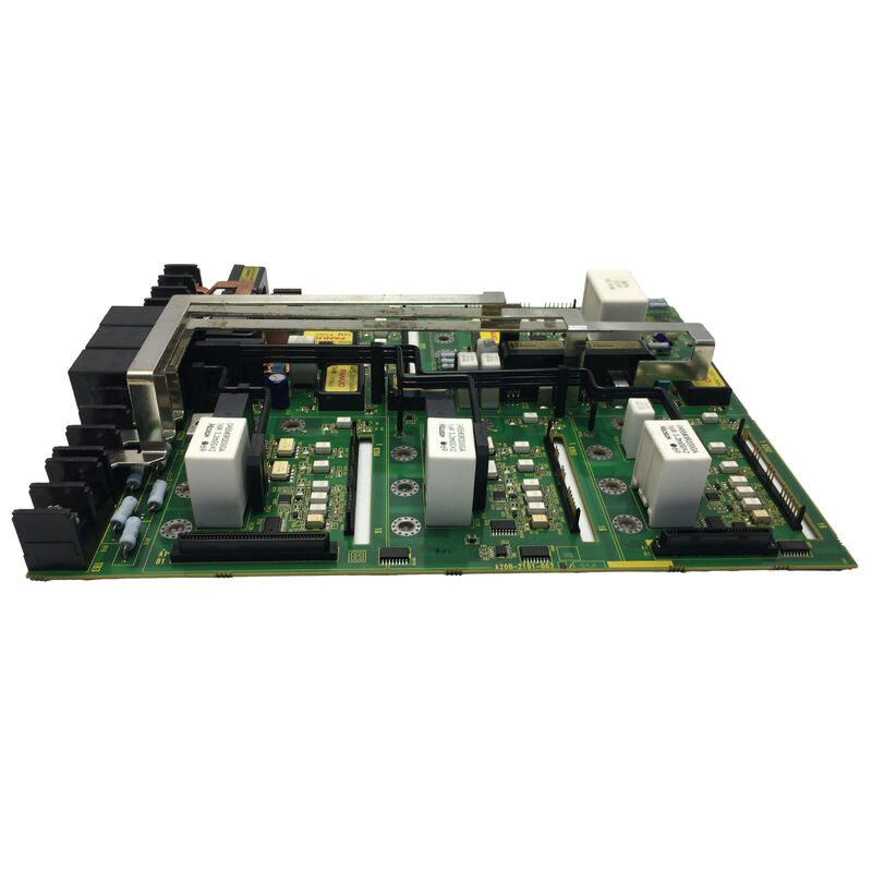
The A20B-2101 series encompasses FANUC's servo and spindle drive circuit boards — the control and power PCBs that form the electronic core of FANUC's servo amplifier and spindle drive modules. This series covers a range of board types serving different drive power ratings, current capacities, and interface generations across the FANUC CNC and robot product families.
Boards in this series carry the gate drive signals, current sensing circuits, protection logic, and communication interfaces that translate position and velocity commands from the CNC into precise motor control outputs. When a servo drive module develops an internal fault, the circuit boards within it are the replacement path — fitting an original FANUC board returns the drive to its specified performance.
Key Product Information
| Parameter |
Value |
| Part Number |
A20B-2101-0922 |
| Series |
A20B-2101 |
| Manufacturer |
FANUC Corporation |
| Type |
Servo Drive PCB |
| Application |
Servo / spindle amplifier systems |
Circuit Boards in Servo Amplifiers — The Control Layer
A FANUC servo amplifier module contains layered PCBs, each handling a specific functional tier:
Power board: Manages the high-voltage, high-current switching for the drive's output stage — gate drive signals to the IGBT switching devices, DC bus monitoring, and regeneration control.
Control board: Processes the CNC's servo commands (via FSSB, Type A, or Type B interface), runs the current control loop at microsecond update rates, handles motor feedback from the encoder, and executes the servo protection logic.
Wiring board: Provides the physical connector interface between external cables and the internal PCB stack.
The A20B-2101-0922 serves one of these roles within the applicable FANUC servo or spindle amplifier module. Its replacement restores the drive's electronic function at board level — avoiding the cost of replacing the complete amplifier module.
Servo Drive Faults That Lead to Board Replacement
Not all servo drive faults require a full amplifier module replacement. Some alarm codes and fault patterns indicate a board-level failure rather than a power device failure:
- Persistent alarm codes that do not match motor or external wiring faults
- Correct motor and wiring, but the drive refuses to clear readiness alarms
- Loss of specific functions (encoder feedback communication, communication interface, current control) with other drive sections remaining functional
- Drive behaviour that changed after a voltage transient on the supply side without obvious physical damage
In these cases, targeted board replacement is the correct repair strategy. The A20B-2101-0922 replacement board restores the failed function without replacing the mechanical and power hardware of the complete module.
Application Scenarios
Servo module internal fault: A CNC machine's servo amplifier trips on an internal alarm that does not match encoder cable, motor, or wiring faults. Board-level diagnosis identifies the A20B-2101-0922 as the failed component. Board replacement restores normal axis operation.
Robot servo drive repair: A FANUC robot controller's servo drive develops an intermittent fault on one robot joint. A20B-2101-0922 replacement resolves the intermittent behaviour and returns the robot to reliable production operation.
Drive board workshop spare: A production facility maintains a set of A20B-2101 series boards as workshop spares for rapid servo module repair, reducing drive repair turnaround time from days to hours.
FAQ
Q1: How do I determine which board within the amplifier module has failed?
Isolate the fault by reading the specific alarm code from the CNC or drive display. FANUC drive alarm codes (SV alarms and SP alarms) are documented in the servo amplifier descriptions manual. Some alarms are specific to the control board, others to the power board. Thermal damage, burn marks, or component discolouration on one board versus another also guide the diagnosis. If the drive's LED display is functional, the alarm pattern helps narrow the fault to a specific board in the stack.
Q2: Does the A20B-2101-0922 contain motor-specific calibration data?
Some FANUC servo amplifier control boards store motor identification data or gain calibration in non-volatile memory on the board. If the replaced board carries motor-specific data, the data must be re-entered or downloaded from backup after fitting the replacement. Check the specific servo amplifier model's maintenance documentation to confirm whether the A20B-2101-0922 carries stored motor data before fitting.
Q3: Is the A20B-2101-0922 used in CNC machining systems, robot controllers, or both?
The A20B-2101 series is used across both CNC and robot product lines, as FANUC's servo drive architecture is shared between platforms. The specific deployment of A20B-2101-0922 depends on the system in which it is installed. The board's position in the spare parts list of the target system confirms whether it serves a CNC axis drive, a spindle drive, or a robot joint amplifier.
Q4: Can the A20B-2101-0922 be sent for repair rather than replaced?
Repair is a cost-effective option when the fault is a discrete component failure (failed IGBT gate driver IC, damaged capacitor, blown protection fuse) that can be identified and resolved at component level. Boards with widespread electrical overstress damage are typically better replaced than repaired.
Q5: What ESD precautions apply to the A20B-2101-0922?
The A20B-2101-0922 contains CMOS logic ICs and driver semiconductors that are susceptible to electrostatic discharge. Handle only with a grounding wrist strap connected to a grounded surface. Store and transport in antistatic packaging. When accessing the servo amplifier module, discharge yourself to ground before touching any PCB. The drive must be fully powered down and DC bus capacitors fully discharged before internal board access — use a DC voltmeter to confirm the DC bus voltage is below 50V before opening the amplifier housing.

 Your message must be between 20-3,000 characters!