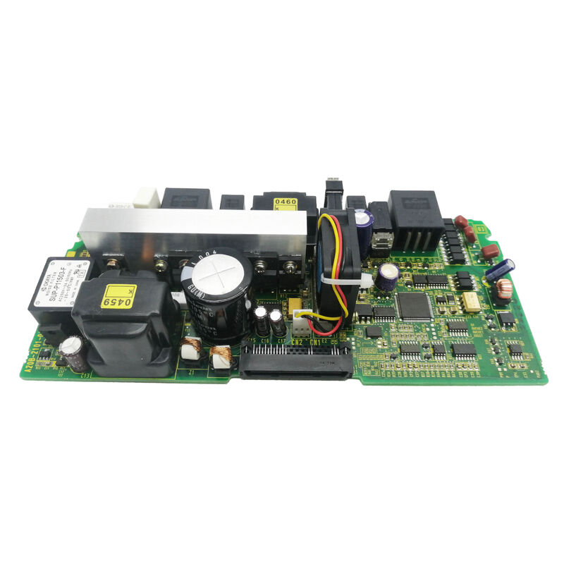
A20B-2101-0950 | FANUC A20B Series Servo Drive Printed Circuit Board — CNC / Robot Servo Amplifier Replacement PCB / Spare Part
Board-Level Serviceability in FANUC Drive Systems
FANUC servo and spindle amplifier modules are designed with multiple removable PCBs rather than a single monolithic circuit assembly. This architecture exists for a practical reason: when a drive fails, the failure is usually localised to one board — the power stage, the control circuit, or the interface board. Replacing only the failed board restores the drive at a fraction of the cost of replacing the complete module.
The A20B-2101-0950 is a circuit board in this servicing layer — a replacement PCB for the specific slot and function it occupies within the applicable FANUC amplifier module. Like other A20B-2101 series boards, it serves within FANUC's servo and spindle drive systems across CNC and robot platforms.
Key Product Information
| Parameter |
Value |
| Part Number |
A20B-2101-0950 |
| Series |
A20B |
| Manufacturer |
FANUC Corporation |
| Type |
Servo Drive PCB |
| Application |
Servo / spindle amplifier systems |
How Servo Board Failures Present at the Machine
A servo drive board failure does not always cause a complete drive shutdown. Depending on which board fails and which component on that board is affected, symptoms can range from subtle to dramatic:
Gradual degradation: Reduced servo accuracy, increased following error, or inconsistent positioning — often caused by component drift in current sensing or feedback processing circuits.
Intermittent alarm: The drive trips occasionally during specific axis movements but clears on reset — suggesting a board component that fails under thermal or load stress.
Immediate trip: The drive alarms immediately on enable, or trips at a consistent point in a machine cycle — a pattern that the CNC's alarm history log can help trace to a specific drive board function.
Loss of communication: The CNC cannot communicate with the drive on its servo bus — an FSSB or Type A/B interface board failure, rather than a power stage failure.
Each pattern points to a different section of the drive electronics, narrowing the replacement target to the A20B-2101-0950 or another board in the module.
Application Scenarios
Servo amplifier overhaul: A FANUC servo amplifier module on a long-running machine tool is overhauled. The A20B-2101-0950 is replaced as part of a board-level refresh, alongside other aged PCBs in the module, to reset the component life of the drive electronics.
Targeted fault repair: A FANUC robot servo module develops a consistent alarm after a period of normal operation. The alarm code points to an internal drive board fault. The A20B-2101-0950 replacement resolves the alarm.
Workshop spare for multiple-axis systems: A system integrator maintaining a plant with multiple FANUC robot stations stocks the A20B-2101-0950 as part of a drive spare parts kit, enabling same-shift repair on servo module failures.
FAQ
Q1: What is the relationship between the A20B-2101-0950 and A20B-2101-0922?
Both are boards in the A20B-2101 series and both serve FANUC servo/spindle amplifier applications. They are different part numbers with different circuit configurations for different amplifier models or slots within amplifier modules. They are not substitutes for each other — the correct board is determined by the specific amplifier model and the slot it occupies. Confirm the exact part number from the installed board label or the amplifier's spare parts list.
Q2: Does the A20B-2101-0950 carry stored parameters from the original drive?
This depends on the board type. Control boards in FANUC servo amplifiers may store motor ID codes, gain tuning data, or protection thresholds in flash or EEPROM. If the original A20B-2101-0950 carried stored data, a replacement board may need data reloaded from backup before the drive returns to optimised performance. Consult the servo amplifier maintenance manual for the specific system to determine if post-replacement data loading is required.
Q3: How are FANUC servo drive alarms decoded to identify the failed board?
FANUC CNC servo alarms (SV alarms) and spindle alarms (SP alarms) are listed in the CNC operator's manual and servo amplifier descriptions manual. Each alarm has a number, a description, and a probable cause list. Many alarm descriptions explicitly identify which hardware section — power circuit, control circuit, encoder interface, or communication interface — is the most likely failure source, directly pointing to the replacement board.
Q4: Is it safe to power the drive with the A20B-2101-0950 removed?
No. Operating a servo amplifier module with any required PCB removed creates an incomplete and potentially dangerous electrical configuration. Missing boards can result in unpredictable switching behaviour, unprotected power stage operation, or complete shutdown failure. Always ensure all required boards are correctly installed before powering any servo amplifier module.

 Your message must be between 20-3,000 characters!