FANUC A20B-2102-0050 | E-Stop PCB — Robot Emergency Stop Control Board, Japan Origin
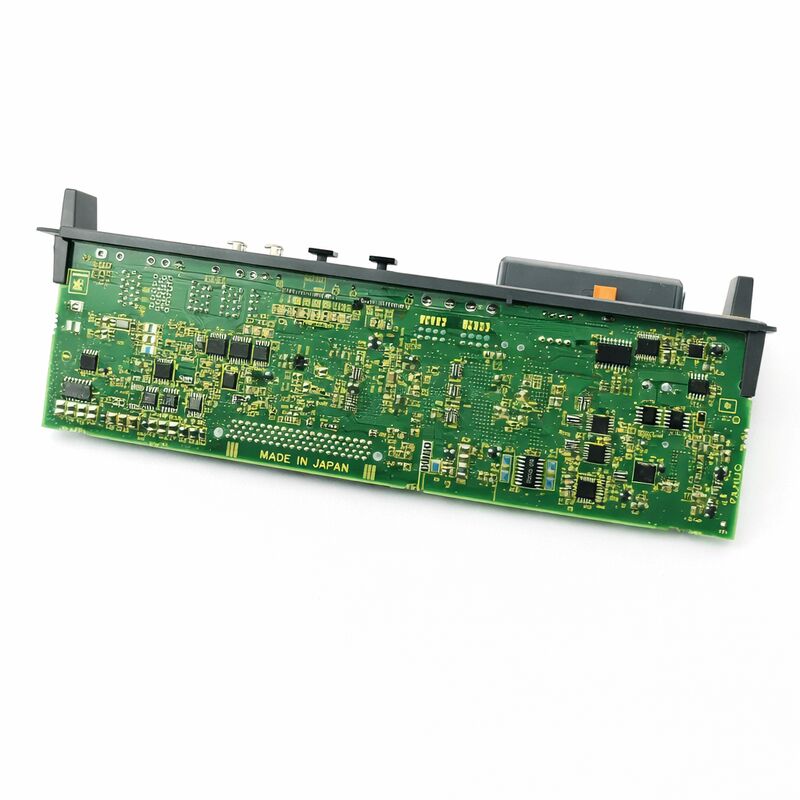
Part Number: A20B-2102-0050
Manufacturer: FANUC Corporation (Japan)
Product Type: E-Stop PCB (Emergency Stop Control Board)
Board Series: A20B-2102
Application: FANUC Robot Controller
Overview
The A20B-2102-0050 is an emergency stop PCB for FANUC robot control systems.
It is the board responsible for managing the hardware-level emergency stop function — the circuit that brings the robot to a safe, controlled stop when an E-Stop signal is activated.
In FANUC robot controllers, this board sits at the intersection of safety logic and servo drive control. It is not a peripheral function. It is a core safety component.
Emergency stop is not simply cutting power to the drives.
A hard power cut to a moving robot at speed can damage mechanical components, leave the robot in an unsafe position, and fail to stop the robot within the required time or distance.
The E-Stop PCB manages a controlled deceleration sequence — commanding the servo drives to execute a rapid but controlled stop before the drive power is removed.
This distinction between a safe stop and a hard cut defines what this board does.
The A20B-2102-0050 is used in FANUC robot controllers and is part of the A20B-2102 board series. When this board develops a fault, E-Stop function is compromised.
The robot controller will alarm on safety circuit faults.
The robot cannot be operated safely without this board functioning correctly.
Key Specifications
| Parameter |
Value |
| Part Number |
A20B-2102-0050 |
| Manufacturer |
FANUC Corporation |
| Product Type |
E-Stop PCB / Emergency Stop Control Board |
| Board Series |
A20B-2102 |
| Application |
FANUC Robot Controller |
| Function |
Emergency stop signal management and drive stop sequencing |
| Origin |
Japan |
| Operating Temperature |
0 – 55°C |
| Storage Temperature |
−20 – 60°C |
| Humidity |
75% RH max (non-condensing) |
| Condition Available |
New / Refurbished / Repaired |
Emergency Stop — What the Board Actually Does
The E-Stop PCB monitors the emergency stop input channels from all connected safety devices: operator E-Stop buttons, safety gates, fence monitors, teach pendant E-Stop, and any other safety inputs wired into the robot cell. When any of these activates, the board initiates the stop sequence.
The sequence matters.
The robot's servo axes are commanded to decelerate — they do not simply drop power.
The stop category implemented depends on the robot's configuration and the safety system design, but in all cases the E-Stop PCB is the hardware that manages this process.
It ensures the servo drive circuits receive the stop command and confirms the execution before drive power is removed.
Fault detection is continuous. The board monitors its own circuits and the safety input channels during normal operation.
A broken safety circuit wire, a contact fault in an E-Stop button, or a failure in the monitoring relay chain will be detected and reported as a safety alarm.
The robot controller will not allow motion when safety faults are active.
This monitoring function is as important as the stop function itself — it prevents the safety system from silently failing.
Safety Circuit Architecture in FANUC Robot Systems
FANUC robot controllers use a dual-channel safety circuit architecture. Safety inputs are read through redundant signal paths.
The E-Stop PCB processes both channels and only allows motion when both channels confirm the safety state is clear. A single-channel fault — one of the two paths reading differently from the other — is detected and alarmed immediately.
This dual-channel approach is a fundamental requirement of industrial safety standards.
A safety system that relies on a single point of detection cannot guarantee detection of its own failure.
The redundant architecture means that even if one signal path develops a fault, the safety system catches it rather than silently passing an incorrect state to the servo drives.
The A20B-2102-0050 implements this architecture in hardware. Its correct function is the foundation of the robot's safety system.
Fault Identification — E-Stop PCB vs. Wiring Faults
When an E-Stop alarm appears on the robot controller, the fault is not necessarily the E-Stop PCB itself.
Safety circuit alarms more commonly originate from wiring faults, faulty safety contacts, deteriorated relay contacts, or broken cable connections than from a failed PCB.
The board should be the last suspect investigated, not the first.
Start with the safety wiring: check all E-Stop button contacts for continuity, check fence monitor relay coils and contacts, check the teach pendant cable and connector, and verify all terminal connections in the safety circuit.
If wiring is confirmed good and the safety alarm persists, the board becomes the fault candidate.
A board that is replaced without addressing an underlying wiring fault will alarm again for the same reason.
Diagnose the root cause before changing hardware.
FAQ
Q1: The robot shows a safety chain alarm. The E-Stop buttons and safety gate are confirmed functional. What should be checked next?
Check the relay contacts on the safety monitoring relays within the controller cabinet — these contacts wear with cycle count and can develop intermittent faults that appear as safety chain alarms.
Also check the teach pendant E-Stop button and its cable continuity.
If all field devices check out, inspect the safety input connector on the A20B-2102-0050 itself for corrosion or damaged pins.
Q2: After replacing the A20B-2102-0050, the robot powers on but the E-Stop alarm persists. What is the cause?
A persisting alarm after board replacement almost always indicates the original fault was in the wiring or a connected safety device, not the board.
The new board reads the same fault as the original.
Methodically test each safety input channel — use the controller's safety circuit diagnostic screen if available to see which specific channel is in fault.
Q3: Can the A20B-2102-0050 be repaired if it has a specific fault rather than replaced?
Component-level repair is viable for known fault modes: failed relay contacts, damaged protection diodes, and deteriorated board connectors are all repairable by experienced technicians.
Boards with fault modes involving proprietary safety monitoring ICs may not be repairable if those components cannot be sourced.
A repair source with specific FANUC robot safety board experience is required.
Q4: The robot was struck by an external collision. After the incident, E-Stop alarms are persistent. Is the PCB likely damaged?
A mechanical impact to the robot can cause loose connectors in the cabinet from vibration and shock, which produces safety circuit alarms.
Before replacing the board, reseat every connector in the safety circuit path and in the cabinet backplane.
An actual E-Stop PCB failure from a collision impact is possible but less common than a connector that was disturbed by the shock.
Q5: The robot is from an older production period. Is the A20B-2102-0050 still available?
This board remains in active supply as a new, refurbished, and repaired component through specialist FANUC parts suppliers.
Older FANUC robot controllers in this family have large installed bases globally, and the supply chain for their key components reflects that demand.
Confirm the exact part number from the label on the installed board before ordering.

 Your message must be between 20-3,000 characters!