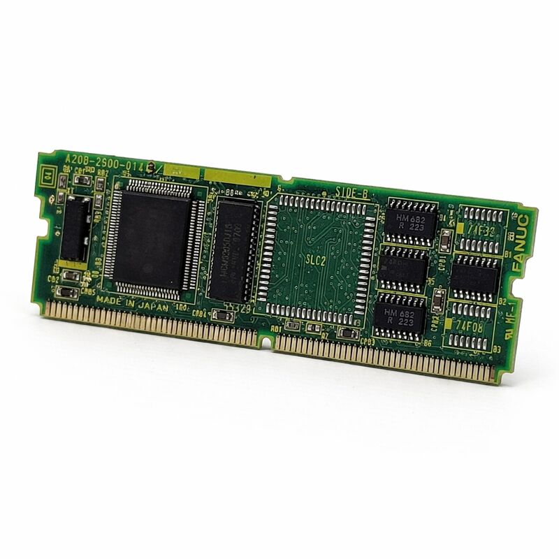
FANUC A20B-2900-0350 | Graphic CPU Module — Series 15-B / 16 / 18, CAP-II Display, Japan Origin
Part Number: A20B-2900-0350
Manufacturer: FANUC Corporation (Japan)
Product Type: Graphic CPU Module (Plug-In PCB)
Board Series: A20B-2900
Compatible Systems: FANUC Series 15-B (Option 1 board), Series 16, Series 18
Display Application: CAP-II, CRT / LCD
Overview
The A20B-2900-0350 is a graphic CPU module for FANUC CNC control systems. It belongs to the A20B-2900 series and plugs into the main board or the Option 1 (OPT1) board depending on the specific controller configuration.
Its primary function is to process and generate the graphical display output for the connected CRT or LCD monitor — it is the computing component that makes the visual interface of the CNC work.
This module is used across FANUC Series 15-B, 16, and 18 CNC systems, enabling these controllers to drive CAP-II display configurations.
CAP-II refers to a specific FANUC CNC display output standard used in this generation of controllers.
The graphic CPU module executes the display rendering tasks — converting the CNC's screen data into the correct signals for the monitor type installed on the machine.
Graphic display functions in a FANUC CNC system are not cosmetic additions.
The operator's entire interface — position display, parameter screens, alarm messages, graphical tool path simulation, and all navigation menus — is generated through the display system.
When the graphic CPU module fails, the operator loses visibility of the machine's state. The CNC may continue to process motion in the background, but the operator cannot confirm status, respond to alarms, or input commands through the screen.
Key Specifications
| Parameter |
Value |
| Part Number |
A20B-2900-0350 |
| Manufacturer |
FANUC Corporation |
| Product Type |
Graphic CPU Module |
| Board Series |
A20B-2900 |
| Compatible Systems |
FANUC Series 15-B, Series 16, Series 18 |
| Display Standard |
CAP-II |
| Installation |
Main board or OPT1 board (controller-dependent) |
| Application |
CRT / LCD display output |
| Origin |
Japan |
| Operating Temperature |
0 – 55°C |
| Storage Temperature |
−20 – 60°C |
| Humidity |
75% RH max (non-condensing) |
| Condition Available |
New / Refurbished / Repaired |
Graphic Processing in CNC Controllers
A CNC controller processes two fundamentally different types of tasks simultaneously. The real-time control tasks — servo position loops, spindle speed regulation, PMC ladder execution — run on the main CPU with tight timing requirements.
Display rendering is computationally intensive but not as timing-critical. Separating these tasks onto different processors is a practical design choice.
The A20B-2900-0350 is the dedicated graphics processor.
It takes data from the main CNC CPU — screen content, cursor position, softkey labels, alarm text, tool path coordinates — and converts this into the video output that drives the display.
Running this work on a separate module keeps the main CPU free for its real-time tasks.
This separation also has a maintenance benefit. A failed graphics module does not take down the CNC's motion control.
The machine may continue running — or can be operated in a limited mode — while the display fault is addressed.
The fault is isolated to the graphics subsystem rather than cascading to the entire control.
CAP-II Display System
CAP-II is the display architecture FANUC used on the Series 15-B, 16, and 18 generation of controllers. It defines the interface between the CNC's display processing electronics and the monitor unit. The A20B-2900-0350 implements the CAP-II display output on the controller side.
Different FANUC controller generations used different display architectures.
Earlier generations used different graphic modules; the HSSB-based systems of the C-series use a different interface still.
The A20B-2900-0350 is specifically the CAP-II solution for the B-series and early numeric-series controllers.
Using a graphic module from a different generation or a different display standard will not produce correct output.
The module's compatibility with both Series 15-B and the Series 16/18 platforms reflects a shared display architecture across these controller families.
The installation position — main board or OPT1 board — varies by specific controller type and configuration.
Confirm the mounting position from the machine's hardware documentation before installation.
Installation Position Variation
The A20B-2900-0350 can install in different positions depending on the controller: directly on the main CPU board in some configurations, or on the OPT1 (Option 1) daughter board in others. The OPT1 board is a expansion board that adds option function slots to the main CPU — the graphic module occupies one of these slots in configurations where the main board does not have a dedicated graphic module socket.
This installation flexibility was intentional in the A20B-2900 series design.
The same graphic module serves multiple controller configurations by adapting to the available slot position.
Before sourcing a replacement, identify which position the currently installed module occupies and confirm that position is available in the controller.
If the OPT1 board itself is also failed or absent, address that first before fitting the graphic module.
FAQ
Q1: The CNC display is completely dark. The machine powers on and axes appear to respond normally. Is the A20B-2900-0350 the likely fault?
A dark display with normal machine function is a strong indicator of a display subsystem fault — the graphic module, the display unit, or the interconnecting cable. Before replacing the module, confirm the display unit receives power (check its own power LED or supply connection).
A display with no power supply won't show anything regardless of the graphic module state.
If power is confirmed, check the signal cable between the controller and the display unit.
If power and cable are confirmed good, the graphic module becomes the primary suspect.
Q2: The display shows partial content — some areas render correctly but others show garbled characters or no data. What does this indicate?
Partial rendering with garbled areas is consistent with a graphic processor fault or a display cable/connector fault.
A fully failed graphic module typically produces a completely blank or fully garbled display, not selective corruption.
Selective corruption is more commonly a cable or connector issue. Check the display cable connectors at both ends and reseat them before replacing the graphic module.
Q3: After replacing the A20B-2900-0350, the display powers on but shows incorrect resolution or display content out of position. What went wrong?
Incorrect display geometry or resolution after a module replacement indicates either a module revision mismatch or a display parameter setting that needs adjustment.
Confirm the replacement module's part number and revision matches the original.
Some FANUC controllers require specific graphic parameters to be set for the display type and resolution; check that these parameters survived the replacement process and match the monitor type installed on the machine.
Q4: The machine uses a Series 16 controller. Can the A20B-2900-0350 from a Series 15-B machine be used as a replacement?
The A20B-2900-0350 serves both Series 15-B (on the OPT1 board) and Series 16/18 (on the main or OPT1 board).
If the source module carries the same part number and revision as the installed one, it is a confirmed hardware match regardless of which controller family it was originally fitted to.
Confirm the installation position matches and verify compatibility through the part number, not the source machine.
Q5: How should a removed A20B-2900-0350 be stored as a spare?
Store in anti-static packaging at a stable room temperature, away from humidity and direct sunlight.
The module contains no battery and no time-critical components that degrade in passive storage — correct anti-static handling and dry storage conditions are the main requirements.
Inspect the board edge connector contacts for oxidation before installation if the module has been stored for several years.
Light oxidation on gold-plated contacts can be cleaned with appropriate contact cleaner before installation.

 Your message must be between 20-3,000 characters!