FANUC A16B-1010-0170 | 0TE Master PCB — Main Control Board, Japan Origin, Discontinued
Part Number: A16B-1010-0170
Manufacturer: FANUC Corporation (Japan)
Product Type: Master PCB / Main Control Board
Designation: 0TE Master PCB
Status: Discontinued by Manufacturer
Overview
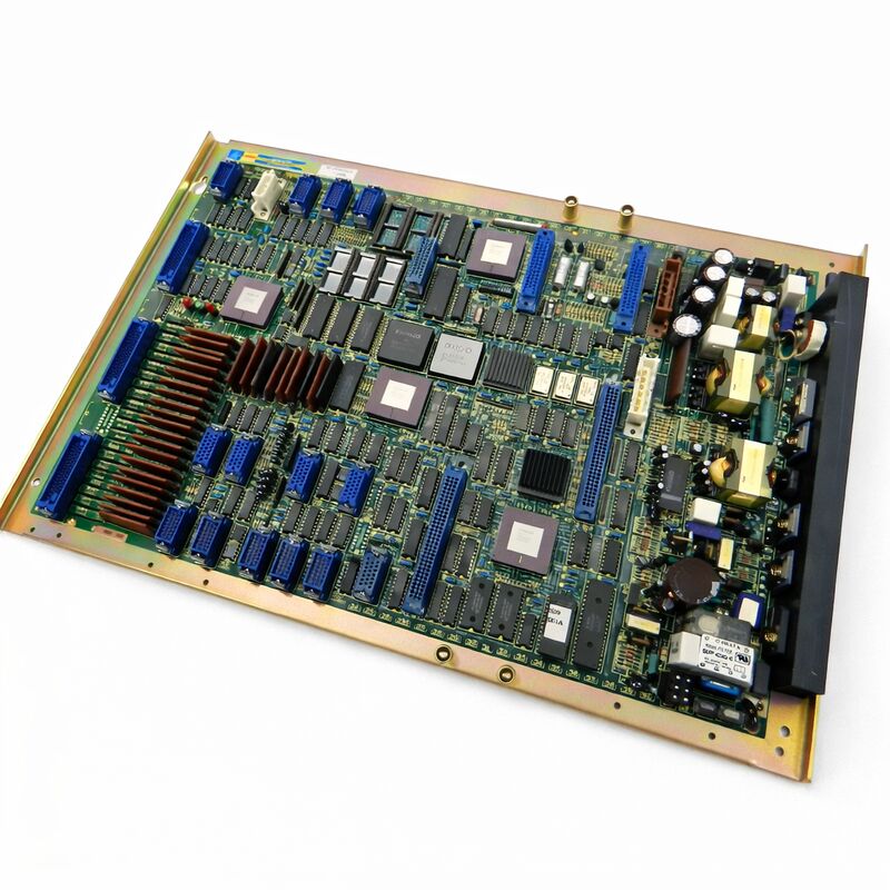
The A16B-1010-0170 is the master PCB for the FANUC Series 0TE CNC control system. In FANUC's Series 0 architecture, the master PCB is the central board — the board that coordinates all CNC functions.
Axis control, spindle command, PMC execution, operator interface, and I/O management all flow through or from this board. When the master PCB fails, the CNC fails completely. No other board in the controller carries the same weight.
The A16B-1010 series covers the master PCB family for FANUC's Series 0 CNC generation. Different suffix numbers identify different variants within the 0 Series family — each tuned for a specific model.
The -0170 is the 0TE variant. It is not interchangeable with boards for other models in the same generation, even those that look physically similar.
This board is discontinued by the manufacturer. FANUC no longer produces it.
The installed base of machines running Series 0TE controls is the only demand that exists for this part — and that demand is real. These machines are still in production across turning centres, EDM equipment, and other applications where Series 0TE was widely deployed.
Key Specifications
| Parameter |
Value |
| Part Number |
A16B-1010-0170 |
| Manufacturer |
FANUC Corporation |
| Product Type |
Master PCB / Main Control Board |
| Designation |
0TE Master PCB |
| Board Series |
A16B-1010 |
| Compatible System |
FANUC Series 0TE CNC |
| Production Status |
Discontinued by Manufacturer |
| Origin |
Japan |
| Operating Temperature |
0 – 55°C |
| Storage Temperature |
−20 – 60°C |
| Humidity |
75% RH max (non-condensing) |
| Condition Available |
New (surplus) / Refurbished / Repaired |
What the Master PCB Controls
The master PCB in a Series 0 CNC system is the system hub. It contains the main CPU, the servo LSI for axis control, and the interface logic that connects to the other boards in the controller. Every other board in the cabinet communicates through or to the master PCB.
Axis position commands originate here.
The servo loop runs here. PMC ladder execution is managed here. When the operator presses a key on the MDI panel, the signal reaches the master PCB. When the machine's M-code calls for coolant, the master PCB processes it.
The scope of this board's role explains why a master PCB fault takes the entire machine offline, while a failure in most other boards affects only a specific function.
On Series 0TE machines — which are typically CNC lathes, turning centres, and wire EDM systems — the master PCB handles the axis configuration appropriate for these machine types.
The 0TE variant reflects the functional and electrical requirements of this specific application.
Sourcing a Discontinued Board
FANUC discontinued the A16B-1010-0170 as the Series 0 generation was superseded by newer control platforms. No new production exists.
Every available unit today is either original surplus (stored new but unused) or a refurbished/repaired unit drawn from the field.
Surplus units are preferable when available.
They have not accumulated operating hours and carry no field failure history. Refurbished and repaired units are valid alternatives when surplus is not available, provided the repair source has genuine experience with FANUC Series 0 master PCBs and tests boards fully before sale.
Counterfeits exist in the market for legacy FANUC boards.
This is not theoretical. Boards with incorrect part numbers on labels, incorrect component populations, or simply failed boards repackaged as functional units do circulate. Purchase from suppliers who can confirm origin and test results.
Installation Considerations
Replacing the master PCB in a Series 0TE controller requires a full system data restore. Parameters, stored programs, and PMC data must be loaded from backup after the board is installed. The board itself installs into the controller rack in the position defined by the machine's documentation.
A parameter set that matches the machine's configuration must be loaded.
This includes machine-specific servo gain settings, axis travel limits, and PMC I/O assignments. Incorrectly loaded parameters can cause immediate axis alarms or unsafe behaviour.
Always verify parameters against the machine documentation before running axes after a master PCB replacement.
FAQ
Q1: The Series 0TE controller powers up but shows a system alarm immediately. Could the master PCB be at fault?
Startup alarms on Series 0 CNC systems often include a two-digit alarm code. Look up the specific code in the Series 0 maintenance manual.
Codes in the 900 series typically indicate hardware faults involving the master PCB or its closely associated circuits. Codes in other ranges may point to memory, servo, or software issues.
The alarm code narrows the diagnosis considerably before assuming a master PCB fault.
Q2: Can the A16B-1010-0170 be repaired at the component level?
Component-level repair is possible for experienced technicians with access to FANUC Series 0 schematics and appropriate test equipment.
Common failure modes include battery circuit failures, capacitor degradation, and servo LSI damage from power transients.
Proprietary FANUC LSI devices on this board cannot be independently sourced — if the servo LSI has failed, board replacement is the only viable path.
Q3: Parameters were not backed up before the master PCB failed. Can they be recovered?
Not directly from a failed board in most cases. If the board has a partial fault — it powers up but alarms — some parameters may still be readable through the CNC interface before the board is removed. A fully dead board yields nothing.
If no backup exists, parameters must be re-entered manually from the machine's documentation or from the machine builder's records.
Q4: Is it necessary to match the board revision level when replacing the A16B-1010-0170?
Revision levels within the same part number typically indicate PCB layout changes that do not affect function.
In most cases, any revision of the A16B-1010-0170 is a valid replacement for another.
However, for machines with very specific software versions or modification histories, confirm compatibility with the service documentation before installation.
Q5: The machine has been idle for several years. The controller powers on but will not run. Is this a master PCB issue?
Extended idle periods cause battery-backed SRAM data to be lost if the backup battery was not maintained.
A machine that cannot run after long storage often has lost its parameter set — not a failed master PCB. Check the backup battery first.
If the battery is dead and parameters are gone, restore from backup or re-enter manually.
If parameters are present and valid but the machine still will not run, proceed to diagnose hardware.

 Your message must be between 20-3,000 characters!