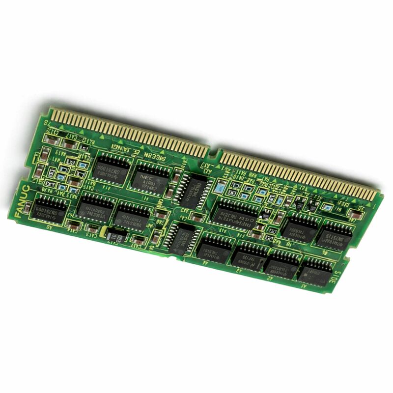
FANUC A20B-2901-0360 | Servo Interface Module PCB — Series 15-B CNC Controls, Japan Origin
Part Number: A20B-2901-0360
Manufacturer: FANUC Corporation (Japan)
Product Type: Servo Interface Module PCB
Board Series: A20B-2901
Compatible Systems: FANUC Series 15-B CNC controls
Application: Servo axis interface for Series 15-B controller
Overview
The A20B-2901-0360 is the servo interface module for FANUC's Series 15-B CNC controller — the highest-performance single-path platform in FANUC's 15-series generation.
This board provides the servo control interface between the Series 15-B's main CPU board and the servo drive units that power the machine tool's axes.
In the Series 15-B's modular board architecture, it is the specific module that translates the controller's interpolated position commands into the servo drive interface signals the connected drive units can act on.
FANUC's Series 15 was the flagship of its CNC generation — a platform designed for complex multi-axis machining with the highest precision requirements.
The Series 15-B was the evolved variant, bringing improved processing speed and enhanced servo control capabilities to the Series 15 architecture.
The machines that used Series 15-B controllers were characteristically complex: large machining centres with 5 or more controlled axes, multi-pallet systems, and precision grinding machines where servo performance directly determined part quality.
The servo interface module is a specific board type in the A20B-2901 family — one that provides the electrical and signal interface between the controller's digital servo commands and the physical drive units in the machine cabinet.
When this module fails, the controller cannot communicate correctly with the servo drives, and axis motion becomes impossible or erratic.
Key Specifications
| Parameter |
Value |
| Part Number |
A20B-2901-0360 |
| Manufacturer |
FANUC Corporation |
| Product Type |
Servo Interface Module PCB |
| Board Series |
A20B-2901 |
| Compatible Systems |
FANUC Series 15-B CNC controls |
| Application |
Servo axis interface |
| Origin |
Japan |
| Operating Temperature |
0 – 55°C |
| Storage Temperature |
−20 – 60°C |
| Humidity |
75% RH max (non-condensing) |
| Condition Available |
New (surplus) / Refurbished / Repaired |
Series 15-B Architecture and the Servo Interface Role
The Series 15-B controller used a distributed board architecture. The main CPU board handled program execution and interpolation. The axis control boards handled the servo loops for groups of axes. The servo interface module — the A20B-2901-0360 — provided the specific interface hardware between the controller's servo control electronics and the physical drive connections.
In FANUC's servo control architecture, the position loop runs in the controller.
The controller calculates where each axis should be, compares that to where it is (from encoder feedback), and generates the velocity command. This velocity command travels through the servo interface module as an electrical signal to the drive unit.
The drive unit converts the velocity command to motor current.
The encoder feedback returns through the same interface module back to the controller.
The servo interface module's job is therefore both outbound and inbound. Outbound: it generates the drive-interface signal from the controller's digital velocity command.
Inbound: it receives the encoder feedback and conditions it for the controller's position measurement circuits. Both paths must function correctly for precise servo control.
Series 15-B in Context
The Series 15-B occupies a distinctive position in the legacy CNC market. It was genuinely capable hardware — the servo control algorithms in the 15-series were sophisticated for their era, supporting high-speed high-accuracy machining that smaller controllers couldn't match.
Machines equipped with Series 15-B controllers were typically high-value production equipment: multi-axis machining centres, precision grinding machines, and complex multi-pallet flexible manufacturing cells.
Many of these machines remain in productive service.
The investment in a Series 15-B equipped machine was substantial, and the machine's mechanical capability often exceeds what the electronic control can provide — the machine simply runs better with a functional 15-B controller than it would with an older replacement.
Maintaining the Series 15-B controller is therefore a practical and economically rational choice for many machine owners.
The A20B-2901-0360, as the servo interface for this platform, is one of the components that makes this maintenance possible.
Its availability in the aftermarket supply chain keeps Series 15-B machines operational.
Diagnosis and Replacement Considerations
When the A20B-2901-0360 develops a fault, the Series 15-B controller loses its ability to interface correctly with the servo drives.
Depending on which circuit in the module fails, the symptoms range from complete axis motion loss (the drives don't receive velocity commands) to servo following errors (the feedback is incorrectly processed and position errors accumulate). In some cases, the failure is intermittent — the module works under some conditions and fails under others, producing erratic axis behaviour.
Before replacing the module, confirm that the connectors associated with the module are clean and fully seated.
A servo interface module fault is often misdiagnosed from a connector that is partially engaged or has developed oxidised contacts.
Reseating the connector resolves many apparent board faults without board replacement.
If the connector is confirmed good and the fault persists, board replacement is the correct response.
After replacement, verify that the axis servo performance — positioning accuracy, velocity stability under cutting load, and encoder feedback processing — is within specification before returning the machine to production.
FAQ
Q1: The Series 15-B controller shows servo following error alarms on all axes simultaneously. The drives and motors appear undamaged. Could this be the A20B-2901-0360?
All-axis simultaneous servo following errors with confirmed good drives and motors is consistent with a servo interface module fault in the shared interface circuitry.
The common path for all axis commands passes through the servo interface module.
If the module's shared circuits have failed — the power supply to the board, the common bus interface — all axes are affected simultaneously.
Confirm connector seating first, then proceed to board replacement if the fault persists.
Q2: Only one axis shows following error while the others are normal. The drive and motor on that axis test as good. Is this the servo interface module?
A single-axis fault with confirmed good drive and motor is ambiguous between the servo interface module's single-channel circuits and the encoder feedback cable for that specific axis. The module has per-axis circuitry for each feedback path.
But encoder cable faults are more common than board single-channel faults.
Inspect and reseat the encoder feedback connector for the affected axis before concluding the board has a per-channel fault.
Q3: The machine runs in automatic mode but produces slightly worse surface finish than it did previously. No alarms are generated. Could the servo interface module be contributing?
Degraded surface finish without alarms, in a machine that otherwise operates normally, points to a subtle change in servo performance.
A slowly failing servo interface module can introduce small amounts of noise or signal distortion into the feedback path, producing minor velocity instability that manifests as surface finish degradation before it generates outright position alarms.
Compare the servo diagnostic data — axis velocity ripple, current draw patterns during cutting — against historical baselines.
Degradation in these values alongside surface finish issues supports the board as a contributor.
Q4: The A20B-2901-0360 is described as discontinued by the manufacturer. Is long-term support for Series 15-B machines still practical?
Long-term support for Series 15-B machines is practical through the aftermarket supply chain.
Tested surplus boards from decommissioned machines, professionally refurbished boards with component replacement and functional testing, and component-level repair services all contribute to the supply.
The Series 15-B installed base is large enough to sustain this supply chain for years to come.
Planning maintenance stock — having a tested spare module available before the installed unit fails — is the most effective approach to long-term Series 15-B support.
Q5: After replacing the A20B-2901-0360, should servo parameters be reloaded?
Servo parameters — the velocity loop gains, position loop gains, and feedforward parameters for each axis — are stored in the controller's non-volatile memory (SRAM or FROM), not on the servo interface module itself.
Replacing the module does not affect stored parameters. However, a complete servo tuning verification is recommended after the replacement to confirm the new module produces equivalent servo performance to the original.
Compare actual servo behaviour against the machine's documented axis performance specifications.

 Your message must be between 20-3,000 characters!