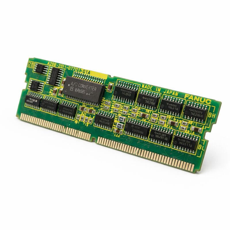
FANUC A20B-2901-0582 | CPU Module PCB with I/O Link 2 Interface — A20B-2901 Series
CPU and I/O Link 2 Master on One Board
The A20B-2901-0582 integrates two functions: the CPU processing that runs the CNC system software, and the I/O Link 2 master interface that manages communication with all connected distributed I/O devices. In a FANUC CNC system, this means the A20B-2901-0582 simultaneously executes the CNC control software and drives the serial bus that connects the controller to remote I/O racks, operator panel I/O, ATC control units, pallet changers, and robotic interfaces throughout the machine.
I/O Link 2 is FANUC's second-generation high-speed serial I/O bus. The master interface on the A20B-2901-0582 polls each connected slave node on every PMC scan cycle, collecting input states and distributing output commands. To the PMC ladder logic, the I/O link 2 devices appear as transparent directly-connected I/O — the serial bus topology is invisible to the PMC program.
As the CPU module, the board executes the control software loaded from the system's FROM modules, manages the memory map, and runs the real-time scheduling for servo interpolation, PMC ladder execution, and operator interface processing.
Key Specifications
| Parameter |
Value |
| Part Number |
A20B-2901-0582 |
| Series |
A20B-2901 |
| Type |
CPU module + I/O Link 2 master |
| Origin |
Japan |
CPU Failure = Complete System Stoppage
Unlike peripheral boards whose failure affects specific functions while the CNC continues running, the CPU module is a single point of failure. A failed A20B-2901-0582 produces a complete control system failure — the CNC does not boot or halts mid-cycle. No degraded-mode operation is possible while the board is absent. For production machines running continuously, holding a verified spare on-site is the recommended strategy.
Parameter Retention and Board Replacement
In the A20B-2901 series architecture, SRAM data (parameters, PMC data, I/O Link 2 address assignments) typically resides in a separate memory module rather than on the CPU board. If the memory module transfers intact to the replacement CPU board, the system can resume with its stored data without a full parameter reload.
Verify this architecture for the specific machine before assuming data transfer applies. In all cases, maintain a complete backup of CNC parameters, PMC ladder program, and I/O Link 2 configuration before any CPU module maintenance.
ESD precautions are mandatory — CPU ICs, CMOS logic, and I/O Link 2 interface circuits are sensitive to electrostatic discharge. Use an ESD wrist strap on a grounded conductive work surface.
FAQ
Q1: The CNC shows an I/O Link 2 alarm and will not complete boot. Is the A20B-2901-0582 faulty?
First, disconnect all I/O Link 2 slave cables and attempt to boot with no slaves connected. If the system boots, the fault is in one of the slave devices or cables — not the CPU board. If the alarm persists with all slaves disconnected, the A20B-2901-0582's I/O Link 2 circuit or CPU function has failed.
Q2: Remote I/O racks are alarming but direct I/O works normally. What does this indicate?
Distributed I/O alarming while direct I/O remains functional points to the I/O Link 2 bus or its master interface. Check I/O Link 2 cable routing and connectors for damage or loose connections. If cables are confirmed good, the I/O Link 2 master interface on the A20B-2901-0582 is the fault source.
Q3: After replacing the board, I/O Link 2 devices show at incorrect addresses. What needs to be done?
I/O Link 2 device addresses are stored as PMC parameters. If the complete PMC parameter backup was not fully reloaded after board replacement, the address map does not match the physical installation. Reload the complete PMC parameter backup. If no backup is available, re-enter device addresses manually from the machine builder's I/O Link 2 configuration documentation.
Q4: Is the A20B-2901-0582 compatible with specific FANUC CNC models?
The A20B-2901 series module interface is compatible with multiple FANUC CNC platforms. The specific compatible platforms for the 0582 variant are defined by the host system's hardware configuration. Verify compatibility through the machine's hardware documentation or FANUC parts compatibility tables before ordering a replacement.
Q5: How should spare parts strategy for this board be managed on a continuously-running production machine?
Hold at least one verified-good A20B-2901-0582 on-site. A CPU module failure causes complete machine stoppage with no workaround while the board is being sourced. Store in ESD-safe packaging in temperature-controlled conditions. Keep the I/O Link 2 configuration documentation and a current parameter backup with the spare board to minimise recovery time after replacement.

 Your message must be between 20-3,000 characters!