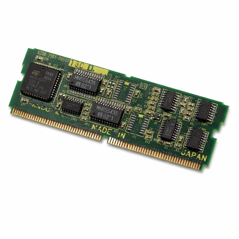
FANUC A20B-2901-0851 | Servo Control Module — 6088 Series Servo Drive, Discontinued
Part Number: A20B-2901-0851
Manufacturer: FANUC Corporation (Japan)
Product Type: Servo Control Module PCB
Board Series: A20B-2901
Application: FANUC 6088 Series Servo Drive
Production Status: Discontinued by Manufacturer
Overview
The A20B-2901-0851 is a servo control module printed circuit board from FANUC's A20B-2901 series, designed for use within the FANUC 6088 series servo drive system. It is the control electronics board that governs how the servo drive interprets position and velocity commands from the CNC, processes feedback from the motor's encoder, and generates the pulse-width modulated output signals that determine how the drive's power stage energises the servo motor.
Servo control modules of this type are peripheral plug-in command boards.
They connect to the CNC's servo interface section and form the direct link between the CNC's motion calculations and the physical drive hardware.
Every axis position command — every increment of table travel, every degree of spindle rotation, every step of the tool path — passes through this board before reaching the motor.
The 6088 series was a well-established FANUC servo drive platform fitted across a broad range of machine tool configurations during its production era.
Many machines built on this drive system remain in production service.
The A20B-2901-0851 has been discontinued by the manufacturer. New units are no longer produced. Replacement supply comes from tested surplus stock and professionally refurbished boards.
Key Specifications
| Parameter |
Value |
| Part Number |
A20B-2901-0851 |
| Manufacturer |
FANUC Corporation |
| Product Type |
Servo Control Module PCB |
| Board Series |
A20B-2901 |
| Compatible Drive Series |
FANUC 6088 Series Servo Drive |
| Board Type |
Peripheral plug-in command board |
| Production Status |
Discontinued by Manufacturer |
| Origin |
Japan |
| Operating Temperature |
0 – 55°C |
| Storage Temperature |
−20 – 60°C |
| Humidity |
75% RH max (non-condensing) |
| Condition Available |
New (surplus) / Refurbished / Repaired |
The Servo Control Module's Role in Drive Architecture
A servo drive system separates its function into two distinct sections. The power section handles the high-current switching that actually energises the motor windings.
The control section — where this board resides — handles all the intelligence: command reception, feedback processing, error calculation, and output modulation.
The A20B-2901-0851 sits in the control section of the 6088 series drive.
It receives velocity or position commands from the CNC through a defined serial or digital interface.
It simultaneously reads the encoder feedback signal from the servo motor, which reports the motor's actual shaft position and velocity in real time.
The board continuously calculates the difference between commanded state and actual state, and adjusts the drive's output to close that gap.
This closed-loop calculation happens thousands of times per second.
The speed and accuracy of the loop directly determine the servo system's positioning accuracy and dynamic response.
A degraded or faulty control board introduces errors into this loop — the servo can no longer correctly follow its command, producing position errors, velocity instability, or outright alarms that stop the axis.
6088 Series Drive Context
The FANUC 6088 series servo drive system used a modular board architecture that matched the FANUC design philosophy of its era. Individual boards within the drive were field-replaceable, allowing targeted maintenance rather than complete drive replacement for every fault.
The A20B-2901-0851 was the plug-in servo control module within this architecture — replacing it restored the drive's control function without requiring replacement of the power hardware.
This board connects to the CNC's main control board through the controller's backplane or direct connector arrangement.
The specific CNC series compatible with the 6088 servo system includes the FANUC controllers current during the drive's production period.
Handling Discontinued Replacement Stock
Since the A20B-2901-0851 is no longer manufactured, sourcing strategy matters. Tested surplus units pulled from decommissioned machines carry known histories and can be evaluated against their previous operating environment.
Professionally refurbished units have been inspected, had consumable components replaced, and have been verified under power before shipping.
When sourcing a discontinued servo control board, request documentation of the test procedure used to verify the board.
A board verified against known-good signals from a compatible drive provides significantly more assurance than one described only as "tested."
Parameter settings from the replaced board should be recorded before removal — some servo parameter adjustments are specific to the motor matched to the drive and must be transferred or restored after a board swap.
FAQ
Q1: The axis shows a servo alarm and will not move. Other axes function normally. Is the A20B-2901-0851 the likely cause?
A servo alarm on a single axis while others operate normally narrows the fault to the components specific to that axis — the servo board, the motor, the encoder, the power module for that axis, or the cable connections. Start by checking the encoder feedback signal and cable continuity.
A clean encoder signal with a servo alarm that points to the control section (drive ready alarm, communication error) makes the control board the primary suspect.
Swap or replace the board as the next diagnostic step.
Q2: After fitting a replacement A20B-2901-0851, the axis moves but position errors are larger than before. What should be checked?
Position errors after a control board replacement point to servo parameter settings. The servo loop gains — position gain, velocity gain, integral term — may need to be restored from the original board's settings.
If the original parameters were not recorded, refer to the machine builder's documentation for the correct values for this motor and drive combination.
Gain settings that don't match the mechanical system produce sluggish response or oscillation.
Q3: The board was found to have a cracked component from a physical impact. Can it be repaired, or does it need full replacement?
A cracked discrete component — a resistor, capacitor, or diode — can often be replaced at the component level by a technician with the correct equipment.
A cracked or physically damaged IC, especially a gate driver or custom FANUC processor, is generally not repairable because the part is not independently available.
Assess the specific damage before committing to component repair vs. board replacement.
Q4: Can the A20B-2901-0851 be cleaned if it has coolant contamination?
Light surface contamination from coolant mist can be addressed with electronics-safe contact cleaner, with the board powered off.
Heavier contamination — where coolant has pooled in connector areas or between IC legs — requires more thorough cleaning and inspection for corrosion damage to the PCB traces.
After cleaning, inspect under magnification before reinstalling.
A board that has been immersed in coolant or has visible trace corrosion is unlikely to be reliably recovered by cleaning alone.
Q5: Is it necessary to back up any data before replacing this servo control module?
The servo control module itself typically does not store parameter data — those are held in the CNC's memory modules.
However, before any board replacement, take a complete CNC data backup including all parameters.
Servo parameters — specifically those matching the drive to the motor — must match after replacement.
Confirm the parameter backup is complete and readable before beginning the physical replacement work.

 Your message must be between 20-3,000 characters!