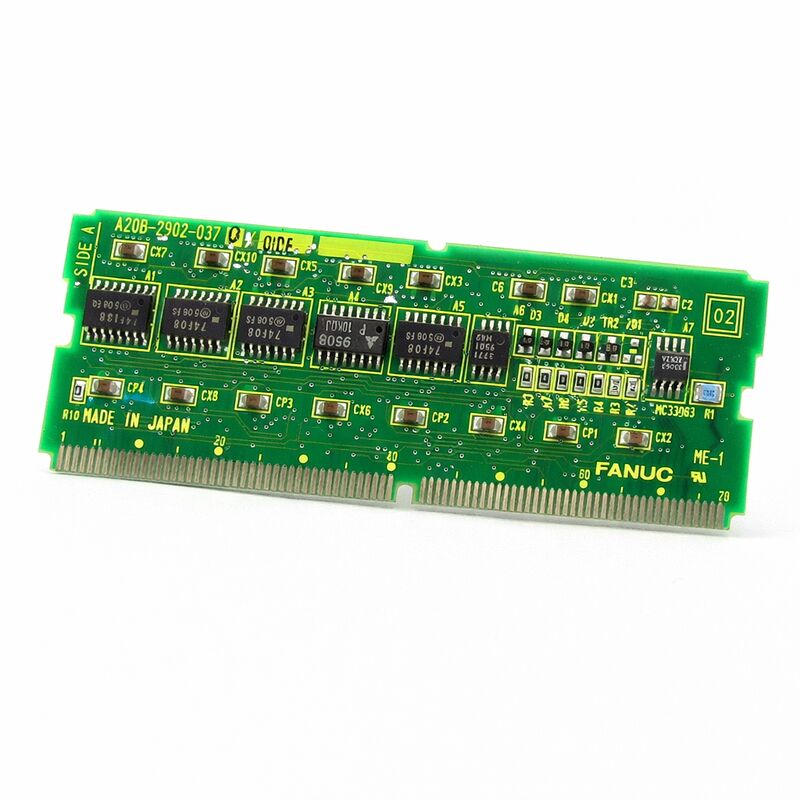
FANUC A20B-2902-0370 | Memory Module PCB — A20B-2902 Series, FANUC CNC Controller, Japan Origin
Part Number: A20B-2902-0370
Manufacturer: FANUC Corporation (Japan)
Product Type: Memory Module PCB (SMD Daughter Board)
Board Series: A20B-2902
Application: FANUC CNC controller memory expansion and storage
Design: SMD plug-in daughter board
Overview
The A20B-2902-0370 is a memory module PCB from FANUC's A20B-2902 series. This series covers a broad family of SMD plug-in memory boards used in FANUC CNC controllers for program storage, parameter retention, system software hosting, and memory expansion.
The A20B-2902-0370 represents one specific variant in this product family, configured to meet the memory requirements of its designated controller platform.
FANUC's CNC controller architectures depend on a layered memory system.
Non-volatile memory holds the software and data that must persist across power cycles. Volatile memory provides the working space for execution. Backup-protected SRAM bridges the two — volatile in its electrical operation, effectively non-volatile through battery protection.
The A20B-2902 series provides the modular physical implementation of these memory layers, with each variant serving specific platforms and capacities.
The -0370 variant sits within the part number range of A20B-2902 modules associated with FROM and SRAM storage functions for FANUC controller platforms in the Series 16 through 21 generation range.
These modules follow the established A20B-2902 series design: compact SMD construction, direct plug-in to the main board socket, and low-power CMOS circuitry that minimises heat dissipation inside the controller cabinet.
Key Specifications
| Parameter |
Value |
| Part Number |
A20B-2902-0370 |
| Manufacturer |
FANUC Corporation |
| Product Type |
Memory Module PCB |
| Board Series |
A20B-2902 |
| Application |
FANUC CNC controller memory |
| Design |
SMD plug-in daughter board |
| Origin |
Japan |
| Operating Temperature |
0 – 55°C |
| Storage Temperature |
−20 – 60°C |
| Humidity |
75% RH max (non-condensing) |
| Condition Available |
New (surplus) / Refurbished / Repaired |
Memory in FANUC CNC Architecture — Why These Modules Matter
A FANUC CNC controller's memory is not a single undifferentiated block of storage. It is a carefully structured hierarchy where different data types live in different memory technologies, because each type of data has different requirements for access speed, write endurance, and persistence.
The CNC operating software lives in FROM.
It was written there during the factory software installation, and it changes only when a deliberate software update is performed.
Flash memory's high endurance for read operations and moderate endurance for write operations makes it ideal for this use — the software is read at every power-on but written rarely.
Parameters and offsets live in battery-backed SRAM.
They change during normal operation — an offset updated after a qualifying cut, a parameter adjusted during maintenance — so they must be in memory that can be written quickly and often, not in Flash.
But they must also persist when the power is off, which is why SRAM backed by a battery is used rather than DRAM.
Some controllers and some memory configurations also use DRAM for working buffers — the interpolation calculations, communication buffers, and PMC execution data that are generated fresh at every power-on and don't need to survive power cycling.
The A20B-2902-0370 serves its specific position in this memory hierarchy for its designated controller platform.
SMD Design and Board Handling
Surface-mount technology defines the physical character of A20B-2902 series boards. All components — memory chips, supporting logic, connector — are mounted on the board surface rather than through holes in the PCB substrate.
This allows a higher component density on a smaller board, which is why these memory modules can pack significant storage capacity into the compact daughter board format.
The SMD construction also means these boards require careful handling.
Components mounted on the PCB surface are more susceptible to physical damage from mishandling than through-hole components.
The board must be handled by its edges.
No component surfaces should be touched with bare hands — skin oils and residue can damage component surfaces or introduce contamination to connector contacts over time.
Static electricity is the other handling concern. CMOS memory components are sensitive to electrostatic discharge.
A static event that would not be noticed as a perceptible shock to a person can still generate enough voltage to damage a logic gate or memory cell.
Anti-static precautions — wrist strap, grounded work surface — are standard requirements when handling any SMD memory board.
Pre-Replacement Checklist
Replacing any A20B-2902 series memory module requires a sequence of steps before the physical work begins. Skipping the preparation creates risk of data loss that requires significant recovery effort.
The first step is always a complete backup. For a combined FROM/SRAM module, the backup must capture both the FROM software (from the FANUC boot screen's memory backup function) and the SRAM data (parameters, offsets, programs, PMC data).
Most FANUC controllers support backup to a SRAM card, a USB memory device, or a PC via RS-232. Use at least one of these methods and verify the backup is complete before removing the module.
The second step is confirming the replacement module's part number.
The A20B-2902 series contains many variants with similar physical appearance but different capacities and compatibility. Only an exact part number match guarantees correct compatibility.
After replacement, the FROM must be rewritten with the correct software files.
Then the SRAM data must be restored from backup. The machine should not be declared ready for production until every data category has been verified against the backup.
FAQ
Q1: What symptoms does a failing A20B-2902-0370 typically produce before complete failure?
Gradual degradation in Flash memory produces intermittent FROM checksum warnings that come and go — the affected cell is marginal, passing some reads and failing others. SRAM degradation shows as occasional random data corruption in parameters or offsets — a value changes unexpectedly between power cycles with no manual intervention. Either symptom warrants module replacement before failure becomes complete.
Once complete failure occurs, the machine cannot start up or run correctly.
Q2: The controller completed a software update, and now shows a FROM error. Did the update corrupt the module?
An interrupted or incorrectly executed FROM write during a software update can corrupt one or more FROM sectors. If the update procedure was interrupted by a power failure, by selecting the wrong software files, or by attempting to load incompatible software, FROM corruption is the likely result.
The FROM must be rewritten from the beginning with the correct software files.
If repeated write attempts fail, the FROM chips have been damaged and the module requires replacement.
Q3: After a machine shutdown for holiday, the controller restores but shows parameter data loss on some axes. The battery reads 3.0V. Is the battery the cause?
A 3.0V lithium cell is at or near the end of its service life — these cells maintain near-nominal voltage until failure is close.
The data loss pattern (affecting some axes but not all) is consistent with an SRAM cell area that lost data when the battery voltage dropped below the retention threshold.
Replace the battery, reload the parameter data from backup, and schedule regular battery checks to prevent recurrence.
Q4: The CNC screen shows "SRAM DATA ERROR" on power-up. The machine has been in storage for 18 months. What happened?
Extended storage with no external power means the backup battery supported the SRAM alone for the entire storage period.
A battery that had limited remaining capacity before storage may have been exhausted during the storage period, causing SRAM data loss.
The SRAM data must be reloaded from backup. Inspect the battery voltage and replace if below 3.2V for a lithium cell.
For long-term storage, the controller should be powered on periodically (every 3–6 months) to maintain battery condition.
Q5: Is it possible to use the A20B-2902-0370 in a Series 18-C controller that currently uses a different variant, if the connector fits physically?
Physical connector compatibility does not guarantee electronic compatibility.
A20B-2902 series variants can share the same connector format while having different memory capacities, different FROM/SRAM ratios, or different interface voltages.
Installing a wrong variant can cause the controller to either fail to recognise the module, operate with incorrect memory capacity allocation, or produce memory faults due to address range mismatches.
Always use the exact part number documented for the specific controller model.

 Your message must be between 20-3,000 characters!