FANUC A20B-2902-0461 | 8MB DRAM System RAM Module — Series 16-C / 18-C CNC, Discontinued, Japan Origin
Part Number: A20B-2902-0461
Manufacturer: FANUC Corporation (Japan)
Product Type: DRAM Memory Module (SMD Daughter Board)
Capacity: 8 MB
Memory Type: DRAM (Dynamic RAM — volatile)
Compatible Systems: FANUC Series 16-C, 18-C CNC
Status: Discontinued by manufacturer
Overview
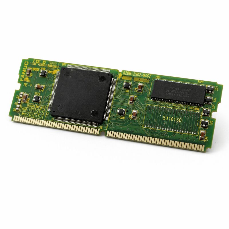
The A20B-2902-0461 is the 8MB DRAM system RAM module for FANUC's Series 16-C and 18-C CNC controllers. It is a compact SMD (surface-mount technology) daughter board that plugs directly into a designated socket on the main controller PCB, providing the dynamic random-access memory the controller uses for all real-time system operations during machine run.
FANUC's Series 16-C and 18-C controllers represented a mature generation of mid-range CNC platforms, widely deployed in turning centres and machining centres during their production era.
The 16-C served multi-axis turning and milling applications; the 18-C targeted compact machining centres requiring robust multi-axis coordinated control.
Both controllers depended on DRAM system memory for the execution of CNC programs, PMC ladder logic processing, data buffering for servo and spindle control, and all runtime calculations. The A20B-2902-0461 is the specific 8MB DRAM module that provides this memory.
DRAM is volatile memory — it requires continuous refresh cycles to retain its content. Power the controller off and the DRAM content is gone.
This is correct behaviour. The CNC's operating system and parameters are stored in non-volatile memory (FROM and battery-backed SRAM).
The DRAM holds the working data generated during a machine cycle: interpolation buffers, communication buffers, and PMC execution data. At power-on, the controller reloads the necessary data from non-volatile memory and begins writing to the fresh DRAM.
This module has been discontinued by FANUC. New stock is no longer produced.
Replacement units come from tested surplus inventory, professionally refurbished boards, or repaired original modules.
Key Specifications
| Parameter |
Value |
| Part Number |
A20B-2902-0461 |
| Manufacturer |
FANUC Corporation |
| Product Type |
DRAM Memory Module (SMD Daughter Board) |
| Capacity |
8 MB |
| Memory Type |
DRAM (dynamic, volatile) |
| Compatible Systems |
FANUC Series 16-C, 18-C |
| Design |
SMT surface-mount plug-in daughter board |
| Status |
Discontinued by manufacturer |
| Origin |
Japan |
| Operating Temperature |
0 – 55°C |
| Storage Temperature |
−20 – 60°C |
| Humidity |
75% RH max (non-condensing) |
| Condition Available |
Tested surplus / Refurbished / Repaired |
DRAM in CNC Controller Architecture
A CNC controller's memory hierarchy serves distinct purposes for different data types. Non-volatile memory — Flash ROM (FROM) and battery-backed SRAM — retains its content when the power is off.
It holds the CNC system software, part programs, parameters, tool offset data, and the PMC ladder. This data must survive power cycles.
DRAM occupies a different place in this hierarchy.
It is fast, dense, and inexpensive — but volatile. The CNC's operating software uses DRAM as its working scratchpad. Interpolation calculations generate position data for each axis at every servo cycle. Spindle command data is buffered. PMC communication data is exchanged.
Communication with I/O devices involves buffer management.
All of this intermediate, transient data lives in DRAM during machine operation.
The system software manages the DRAM allocation and refresh automatically.
The operator and maintenance technician are not normally aware of the DRAM's operation — until it fails. When the DRAM fails, the system detects the failure through its memory self-test routines.
The most common alarm is a parity error: the controller detects that data read from a DRAM address does not match the parity bit written with the data.
This alarm appears at power-on during the controller's memory test, or occasionally during operation if a cell fails intermittently under thermal stress.
Parity Error Alarms and the Replacement Decision
A DRAM parity error alarm is a reliable indicator of memory module failure. FANUC's i/C-series controllers perform memory tests during power-on initialization. If the DRAM module fails this test, the alarm is generated and the controller cannot proceed to its normal operating state.
The machine cannot be jogged, programmed, or run until the fault is corrected.
Intermittent parity errors — errors that appear occasionally during operation but not consistently at power-on — suggest a marginal DRAM cell. The cell may pass the power-on test when the module is cold, but fail during operation as the module warms up.
This thermal dependence is a common DRAM aging pattern. If the parity error appears only after the controller has been running for some time, this thermal failure mode is likely.
Before replacing the module, a complete CNC data backup is essential.
While the DRAM itself is volatile and contains no persistently stored data, the module replacement process requires opening the controller and handling the main board.
Any accidental disturbance to the battery-backed SRAM connections or the main board can cause data loss from the non-volatile memory.
Back up all programs, parameters, PMC ladder, and tool data to a PC or USB storage device before starting any work.
SMD Construction and Handling
The A20B-2902-0461 uses surface-mount construction. The DRAM chips and all associated components are mounted directly on the small board's surface, with no through-hole components.
The board mates with its socket through a fine-pitch connector. This connector is not as mechanically robust as a large edge connector — it can be damaged by misalignment or forced insertion.
Handle the board by its edges. Never touch the component surfaces or the connector contacts.
Use anti-static precautions throughout — an ESD event during handling can damage DRAM cells that then fail intermittently in service, producing the same parity error symptoms the replacement was intended to cure.
Align the connector carefully before pressing the board into its socket. Confirm full engagement.
If the board is not fully engaged, the controller may power on but report communication errors or unexpected memory alarms that don't correspond to the board's actual condition.
FAQ
Q1: The CNC shows a DRAM parity error alarm at power-on. The alarm appears consistently every startup. How confident can we be that it is the A20B-2902-0461?
A consistent parity error at every power-on is a strong indicator of a failed DRAM module.
The controller's memory self-test executes the same test sequence at every power-on, and a failed cell fails the same test every time.
Before ordering a replacement, visually inspect the module and its socket for any contamination or physical damage.
If neither is found, the module has failed internally and requires replacement.
Q2: The parity alarm appears only after the machine has been running for about 30 minutes. Power cycling clears it temporarily. What is happening?
This is classic thermal-mode DRAM failure. The module's cells are marginal — they pass the cold power-on test but develop timing errors as the device heats up during operation. The cell's refresh characteristics degrade with temperature, and eventually the data read does not match the written parity.
Powering off lets the module cool, allowing it to pass the cold test again. The module is failing and requires replacement.
Do not continue operating with this condition — data integrity during machining cannot be guaranteed when the DRAM is thermally unstable.
Q3: The backup was taken before module replacement. After installing the replacement A20B-2902-0461, does any data need to be reloaded?
The DRAM module itself contains no persistent data — the replacement board starts blank, which is correct. However, if the main board was disturbed during installation, parameters stored in battery-backed SRAM could be corrupted.
After installation, verify that all parameters, tool offsets, and PMC data are intact by checking key values against the backup.
If any values are incorrect or alarms appear after restart, restore from backup.
Q4: Are there any other 8MB DRAM modules in the A20B-2902 series that can substitute for the -0461 in a Series 18-C?
The A20B-2902 series includes several 8MB DRAM variants matched to different controller generations and main board socket configurations. The -0461 is specific to the Series 16-C and 18-C platform.
Other variants in the same series (such as -0630 for 16i/18i) use different board dimensions, connector configurations, or DRAM specifications.
They are not substitutable without confirmed compatibility. Always source the exact part number for the installed controller.
Q5: Is it possible to repair the A20B-2902-0461 at component level rather than replacing the whole board?
DRAM chips are commodity components, and a skilled board repair technician can sometimes identify and replace a specific failed chip on a DRAM module. Whether this is practical depends on the chip's package type and the availability of a matching component.
On surface-mount boards, chip replacement requires precision SMT rework equipment.
If a qualified repair service offers a tested repaired module with a warranty, this is a viable and cost-effective alternative to sourcing a tested surplus original.

 Your message must be between 20-3,000 characters!