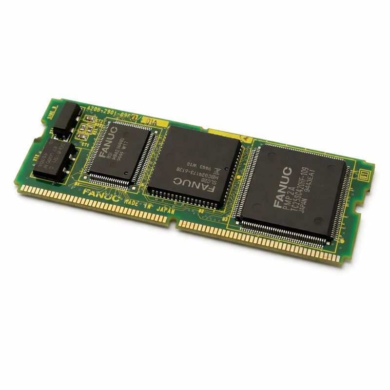
FANUC A20B-2902-0480 | PMC-RB5 / RB6 Control Module with I/O Link — Series 16 / 18 / 20 Model C
Part Number: A20B-2902-0480
Manufacturer: FANUC Corporation (Japan)
Product Type: PMC Control and Memory Module — SMD Plug-In Daughter Board
Operating Temperature: 0–55°C
Two Functions in One Module
The A20B-2902-0480 is the PMC control and memory module for FANUC's Series 16/18/20 Model C controllers. It plugs into the PMC/Conversational board and provides two things simultaneously: the memory the PMC needs to run its ladder program, and the I/O Link interface that connects the controller to distributed I/O devices across the machine.
The memory side: 32 KB SRAM stores the ladder program itself — the relay logic that defines the machine tool's automation: tool change sequences, safety interlocks, mode switching, M-code responses. 256 KB DRAM provides working memory for PMC execution — signal register states, timer values, counter values, and data tables that the ladder updates every scan cycle.
The I/O Link side: Every signal between the operator panel and the CNC travels through this module's I/O Link interface. Mode switches, feedrate overrides, cycle start inputs, panel lamp outputs — all of it is carried on a single I/O Link serial bus that the PMC module polls every scan cycle. When this interface fails, all panel communication is lost simultaneously. The machine stops responding to operator inputs and all panel indicators de-energise. That total panel loss, accompanied by an I/O Link communication alarm at the CNC, is the fault pattern that points specifically to this module rather than to an individual I/O board or a wiring fault.
RB5/RB6 — What the PMC Version Determines
The PMC-RB designation identifies the ladder language specification and execution architecture. The version loaded in this module determines the maximum ladder step count the PMC can run, the execution speed, and the I/O Link addressing. It is not interchangeable with different PMC versions. A replacement module must match the original RB5 or RB6 version — and the PMC ladder program, stored separately in the controller's FROM module, is not affected by replacing this module.
Key Specifications
| Parameter |
Value |
| Part Number |
A20B-2902-0480 |
| PMC Type |
PMC-RB5 / PMC-RB6 |
| SRAM |
32 KB |
| DRAM |
256 KB |
| Interface |
I/O Link |
| Compatible |
Series 16/18/20 Model C |
| Mounts On |
PMC/Conversational board |
| Origin |
Japan |
FAQ
Q1: The operator panel is completely unresponsive and the CNC shows an I/O Link error. Is this the A20B-2902-0480?
Complete panel loss with an I/O Link alarm points to the PMC module's I/O Link interface. First check the I/O Link cable connection at the module — a loose connector produces identical symptoms to a failed interface circuit. If the cable is fully seated and the error persists, the module's I/O Link circuit has failed. Verify by swapping a tested spare module if available.
Q2: A specific automatic cycle step never completes — the machine stops at the same point every time. Is this the PMC module?
A single step that always fails is unlikely to be a module hardware fault. PMC module failures tend to be broad — affecting many functions simultaneously. A single-step failure points to a specific input the ladder is waiting for. Use the PMC ladder diagnostic screen to identify which signal the ladder expects at that step and trace that signal from its source.
Q3: Does replacing the A20B-2902-0480 require reloading the PMC ladder program?
No. The PMC ladder is stored in the CNC's FROM module, not in this module. Replacing the A20B-2902-0480 does not affect the stored ladder. After replacement, power-cycle the controller and confirm I/O Link communication is restored on the PMC diagnostic screens. Verify the replacement is the correct RB5 or RB6 version before installing.
Q4: The controller shows a DRAM-related PMC alarm. Does 256 KB DRAM indicate insufficient capacity?
For standard Series 16/18 Model C applications, 256 KB is the designed specification for the RB5/RB6 PMC. A DRAM alarm on a correctly specified system indicates DRAM cell failure, not insufficient capacity. Replace the module.
Q5: Can the PMC ladder from a Series 16-C be used directly on a newer FANUC controller?
No. The ladder written for PMC-RB5/RB6 uses the addressing and instruction syntax specific to that PMC generation. A newer controller uses PMC-SB or a later version with different addressing conventions. The ladder must be converted or rewritten for the new platform. Keep the original file as the functional specification.

 Your message must be between 20-3,000 characters!