FANUC A20B-2902-0501 | 8MB FROM + 256K SRAM Combined Memory Module — Series 16 / 18 / 21 CNC
Part Number: A20B-2902-0501
Manufacturer: FANUC Corporation (Japan)
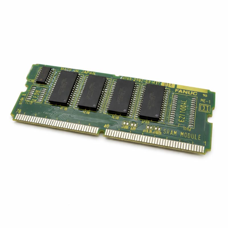
Product Type: Combined FROM + SRAM Memory Module (SMD Daughter Board)
Two Memory Types, Two Different Jobs
The A20B-2902-0501 integrates two functionally distinct memory types on a single SMD daughter board, and understanding the difference between them is essential for correct maintenance and replacement decisions.
FROM (Flash ROM — 8 MB): Stores everything the CNC needs to boot and run — the operating system software, PMC ladder programs, and machine builder application software. Flash is genuinely non-volatile: its content survives complete power loss, battery depletion, and extended storage without degradation. A blank replacement module has empty FROM — the CNC software and PMC ladder must be reloaded from backup before the machine can operate. FROM failure typically presents as a checksum error at boot or a persistent startup failure.
SRAM (256 KB — battery-backed): Stores the data that changes during normal machine use — parameters, tool offset tables, work coordinate offsets, and tool usage logs. This data must survive each power cycle between shifts, which is what the backup battery provides. When the battery voltage falls below the retention threshold, SRAM content is lost. FANUC controllers generate a low battery warning well before this point. Replace the battery with the controller powered on — replacing with power off, or ignoring the warning until the battery is dead, means restoring all parameters and offsets from backup.
The two sections are electrically independent. FROM alarms (checksum, boot failure) point to the FROM section; SRAM alarms (parameter loss, battery warning before data corruption) point to the SRAM section and battery.
Replacement Considerations
A new A20B-2902-0501 arrives with blank FROM and blank SRAM. Before the machine can run, the CNC software must be reloaded into the FROM, and all parameters, offsets, and work coordinates must be restored from backup. A complete data backup before any memory module work is not optional — it is the only way to recover the machine's configuration if the original module fails in a way that prevents reading it.
Verify FROM module compatibility before substituting: the A20B-2902-0501 has 8 MB FROM. The -0341 variant has 4 MB. The loaded software image must match the module capacity — check the Series 16/18/21 maintenance documentation before substituting a different variant.
Key Specifications
| Parameter |
Value |
| Part Number |
A20B-2902-0501 |
| FROM |
8 MB (Flash ROM, non-volatile) |
| SRAM |
256 KB (battery-backed) |
| Platform |
Series 16, 18, 21 CNC |
| Design |
SMD plug-in daughter board |
| Origin |
Japan |
FAQ
Q1: The CNC shows a FROM checksum error at power-on and cannot complete startup. Is the module faulty?
Persistent FROM checksum errors across multiple power cycles indicate corrupted or failed FROM. First attempt to rewrite the FROM via the BOOT screen with the correct software files. If the module rejects the write or errors persist after a successful write, the FROM hardware has failed and the module needs replacement.
Q2: The controller shows a low battery warning. How urgently does the battery need to be replaced?
The warning appears before the battery reaches the critical retention threshold — typically allowing days to weeks of continued operation, depending on battery age and cabinet temperature. Do not wait. Replace the battery with the controller powered on so the SRAM content is maintained through the battery swap.
Q3: After fitting a new module, the machine shows parameter errors and all offsets are zero. Is this normal?
Yes — a new module arrives with blank SRAM. All parameters, tool offsets, and work coordinates must be restored from the backup taken before the module was removed. This is the expected result and underlines why the backup must be taken before, not after, the module fails completely.
Q4: Can the A20B-2902-0501 (8 MB FROM) replace the A20B-2902-0341 (4 MB FROM) in a Series 16-C?
Not without verification. The loaded software image must be sized for the module's FROM capacity, and the controller must support the 8 MB variant. Consult the Series 16-C maintenance documentation for compatible FROM module options before substituting a different capacity.
Q5: SRAM data was lost during a power interruption even though the battery tested good. What else could cause this?
Possible causes with a confirmed-good battery cell: a broken connection in the module's battery backup circuit (the cell voltage is correct but the circuit path is open), an exceptionally fast power dip that pulled SRAM supply below retention voltage faster than the battery could respond, or physical connector disturbance during the interruption. Inspect the module's connector contacts and the battery circuit's solder connections.

 Your message must be between 20-3,000 characters!