FANUC A20B-3300-0091 | 7.2-Inch Monochrome Character Display PCB — For Series 16i / 18i / 21i CNC, LCD/MDI Unit, Character-Only Output, Rear of Operator Panel
Overview
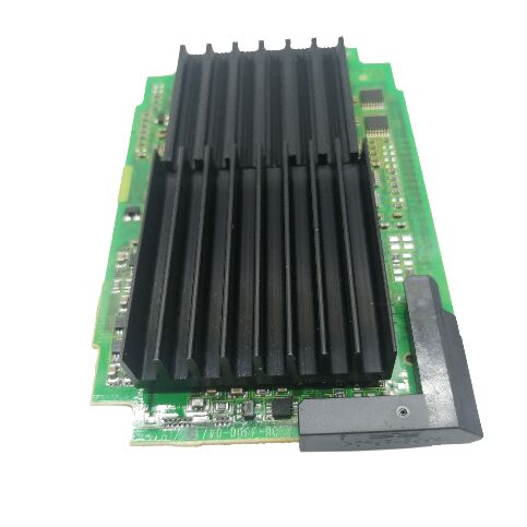
The FANUC A20B-3300-0091 is the display driver PCB for the 7.2-inch monochrome character LCD in FANUC's i-series CNC systems.
It sits behind the LCD panel inside the operator station, plugged into the main CPU board — physically attached to the rear of the LCD/MDI unit and in direct contact with the backplane that connects it to the CNC's central processing logic.
Every time an operator reads a programme number, checks a parameter, views an alarm message, or steps through an offset table on a 7.2-inch mono i-series control, the data passes through this PCB's video generation circuitry before appearing on screen.
The "character only" designation is the key differentiator between the A20B-3300-0091 and the graphic display variants in the A20B-3300 series. Character display PCBs generate video output using a character ROM — a lookup table mapping ASCII or similar character codes to pixel patterns.
The CNC sends character codes, and the display board converts them to dot patterns in the LCD's scan cycle.
This approach is computationally efficient and produces sharp, readable text for the data-dense screens that operators use most — programme numbers, coordinates, alarm codes, spindle speed readouts — but cannot render freeform bitmap graphics.
Graphic display variants (found in colour or graphic-capable mono displays on the same machines) carry additional GPU-class circuitry to render tool-path simulations, waveform graphics, and graphical help screens.
The A20B-3300-0091 does not carry this circuitry — and a machine fitted with this PCB will present a control that has no graphic simulation screen, even if the CNC software's option settings are configured to enable graphics.
For sites where operators rely on text-only workflows, this limitation is invisible; for machines where graphic toolpath display is an operational expectation, the appropriate graphic-capable display PCB is required instead.
Key Specifications
| Parameter |
Value |
| Display Size |
7.2 inches |
| Display Type |
Monochrome character (no graphics) |
| Compatible Series |
16i, 18i, 21i |
| Board Position |
Rear of LCD/MDI unit, on main CPU board |
| Interface |
Backplane plug-in |
| Status |
Discontinued spare |
| Origin |
Japan |
Where the A20B-3300-0091 Fits in the 16i / 18i / 21i Display Ecosystem
The FANUC i-series (16i, 18i, 21i) offered operators a range of display options at the time of machine purchase, and the display PCB fitted at the factory reflected the option level purchased.
At the base end: 7.2-inch monochrome character display — the A20B-3300-0091. Moving up: 7.2-inch monochrome graphic display (adds toolpath simulation and graphic diagnostics).
At the top: 9-inch or 10.4-inch colour display (full colour graphics, highest resolution).
Each level requires a different display PCB on the main CPU board, and these PCBs are not interchangeable — the LCD panel, the display PCB, and the CNC software's display option settings must all match.
A machine tool purchased with the character-only display option may have additional software options (graphic option, DNC2, etc.) that are not activated in the installed configuration. Changing the display hardware from character to graphic — replacing the A20B-3300-0091 with an appropriate graphic PCB — does not automatically activate graphic software features. The CNC's option byte settings and potentially the FROM module's option registration must also be updated, which typically requires FANUC's involvement or an appropriate option key.
What Appears on a Character-Only Display
The character display supports everything an operator needs for day-to-day CNC machine operation:
Programme selection and content: Part programme numbers (Oxxxx format), programme blocks (G, M, T codes in text), and programme directory listings.
Position display: Machine coordinates, workpiece coordinates, and remaining travel — updated every CNC scan cycle, appearing as numeric text.
Alarm and message display: System alarms (PS alarms, SV alarms, OT alarms) with alarm number and text description, operator messages written in the PMC ladder.
Parameter screens: All CNC parameters (numbered 0 through 9999+) displayed as numeric values with parameter numbers, navigable through the MDI keypad.
Offset display: Tool geometry offsets, wear offsets, work coordinate offsets — all numerical tables read directly from offset memory.
Diagnosis and servo screens: Servo load meter values, spindle speed, and diagnosis data in numeric form.
None of these require bitmap graphics.
Operators who have worked on character-only FANUC controls consistently report no practical workflow limitation for standard turning, milling, and grinding operations.
FAQ
Q1: What visible symptoms on the operator panel indicate that the A20B-3300-0091 PCB has failed, rather than the LCD panel itself?
The key diagnostic is whether the LCD backlight is on. If the backlight illuminates (panel glows) but no characters appear, the display PCB is the likely cause — the LCD panel and its inverter are functioning, but the video signal from the display PCB is absent or corrupted.
If the backlight is off entirely, a failed backlight inverter or LCD panel power circuit is more likely the cause.
Other indicators of display PCB failure: scrambled or partially displayed characters (some rows correct, others garbled), blank screen with backlight on, or a static pattern that does not update when the MDI keys are pressed. Swap the board with a known-good unit to confirm.
Q2: The machine currently has the A20B-3300-0091 (character display). Can it be upgraded to a graphic display by replacing this PCB?
Physically, yes — the graphic-capable display PCB for the same screen size fits the same backplane slot.
Functionally, the upgrade also requires the CNC's display option to be activated in the system software (FROM module), which is an option registration process that FANUC controls through its option key system.
The graphic display PCB alone, fitted to a machine that does not have the graphic option registered in its system, will not produce graphic output.
If the machine was originally ordered without the graphic option, restoring the character display with a like-for-like A20B-3300-0091 replacement is the straightforward path.
If a genuine graphic display upgrade is needed, the option registration must be addressed through FANUC or a FANUC-authorised source.
Q3: Is the A20B-3300-0091 interchangeable with other A20B-3300 display PCBs for the 7.2-inch mono display?
Not directly — within the A20B-3300 series, variants differ in their display interface protocol, resolution handling, and option compatibility.
A graphic-capable 7.2-inch mono PCB (such as A20B-3300-0154 or others) carries different circuitry and cannot substitute for the character-only A20B-3300-0091 without the corresponding software option settings.
Within the character-only variants, closely related part numbers (sharing the same -3300-00xx suffix structure) should be verified against the specific machine's main CPU board and software version before substitution.
Consulting the FANUC operator panel connection manual (B-63003EN or equivalent for the specific series) or the machine tool builder's wiring documentation confirms which display PCB variant is correct.
Q4: Does the A20B-3300-0091 retain any machine-specific data (parameters, programmes) that must be saved before removal?
No. The display PCB is a stateless video output device — it carries no user data, no machine parameters, and no programme storage. It simply converts the data it receives from the main CPU board into video signals. Removing and replacing it requires no data backup specific to this board.
However, if the board is being replaced as part of a broader main CPU board replacement, all machine parameters, programmes, and PMC ladder data must be backed up from the CNC before the main board is disturbed. The display PCB replacement itself is non-destructive to any stored data.
Q5: What precautions are needed when replacing the A20B-3300-0091?
Power down the machine completely and wait for the DC bus (if any spindle or servo amplifiers are connected) to discharge before opening the operator panel. The display PCB is accessed from the rear of the LCD/MDI unit — typically by removing the rear cover of the control panel housing.
The PCB connects through a backplane edge connector and may be secured by one or two screws. ESD precautions (antistatic wrist strap, antistatic mat) are essential when handling the board.
Ensure all connector orientations match before seating the replacement board — incorrect seating on the backplane can damage the connector pins. Power up and confirm character display functionality before closing the panel.

 Your message must be between 20-3,000 characters!