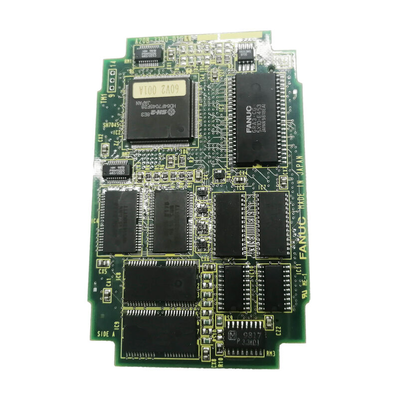
FANUC A20B-3300-0154 | 7.2-Inch Monochrome Graphics Module — Series 16i / 18i / 21i / 20i, Japan Origin
Part Number: A20B-3300-0154
Manufacturer: FANUC Corporation (Japan)
Product Type: Monochrome Graphics Display Control PCB (GPU Card)
Board Series: A20B-3300
Display Type: 7.2-inch STN monochrome LCD
Compatible Systems: FANUC Series 16i, 18i, 20i, 21i
Overview
The A20B-3300-0154 is the graphics processing module for FANUC's 7.2-inch monochrome LCD operator panel fitted to Series 16i, 18i, 20i, and 21i CNC controllers. It is the dedicated GPU card — a plug-in board that mounts on the back of the i-series main board — responsible for all graphics processing and display output delivered to the 7.2-inch STN mono panel visible to the operator at the machine.
Every visual element on the CNC operator interface passes through this board.
The machining program list, the axis position display, alarm text, parameter screens, and the graphical tool path representation are all rendered by this module.
The main CPU board handles program execution, motion interpolation, and PMC processing.
This graphics board handles the separate task of converting that data into the dot-matrix output sent to the LCD panel.
The separation of graphics processing into a dedicated board is a deliberate part of FANUC's i-series architecture. The main board CPU is not burdened with display rendering calculations — those run on the A20B-3300-0154's own dedicated processing hardware.
This allows the CNC's main processor to maintain consistent interpolation performance regardless of what is happening on screen.
The board mounts on the reverse face of the main CPU board, inside the yellow-framed backplane of the i-series basic unit.
It plugs into a dedicated socket and is secured with four spacer clips.
Its physical position keeps it protected from the machine environment while remaining accessible for replacement when required.
Key Specifications
| Parameter |
Value |
| Part Number |
A20B-3300-0154 |
| Manufacturer |
FANUC Corporation |
| Product Type |
Monochrome Graphics Display Control PCB |
| Board Series |
A20B-3300 |
| Display |
7.2-inch STN monochrome LCD |
| Compatible Systems |
FANUC Series 16i, 18i, 20i, 21i |
| Installation |
Plug-in module on main CPU board rear |
| Origin |
Japan |
| Operating Temperature |
0 – 55°C |
| Storage Temperature |
−20 – 60°C |
| Humidity |
75% RH max (non-condensing) |
| Condition Available |
New (surplus) / Refurbished / Repaired |
What the 7.2-Inch Mono Display Means for Machine Operation
FANUC equipped many of its i-series compact CNC units with 7.2-inch STN monochrome LCD panels.
The monochrome display uses a single-colour matrix — typically white characters and graphics on a dark background — rather than the backlit colour panel used in larger i-series configurations.
This keeps the panel unit compact and suits environments where a small footprint matters more than colour display.
The operator can read program contents, edit part programs, monitor axis positions, review and set parameters, and check alarm messages. For toolpath display, the 7.2-inch mono screen shows wire-frame graphics of the programmed path — adequate for verifying program trajectories before cutting.
The graphics module handles this rendering: it receives the toolpath data from the main CPU and converts it to the monochrome dot-matrix signal the panel displays.
When the A20B-3300-0154 fails, the display shows specific symptoms.
A blank screen with the CNC otherwise operating normally is the most common. The panel's backlight may remain on — showing a faint glow — but no characters or graphics appear, because the graphics module is not producing output.
Occasionally a partial display failure appears: some content renders while other screen areas remain blank. These failure patterns help distinguish a graphics module fault from a panel unit fault.
Installing and Removing the Graphics Module
FANUC's i-series main boards use a standardised mounting method for plug-in modules. The A20B-3300-0154 is held to the main board by four spacer clips arranged at the board's corners. To remove the board, each spacer clip's claw is pulled outward to release the latch, and the board lifts away from the socket.
Reinsertion requires aligning the board's connector with the main board socket and pressing down until all four clips latch.
The connector alignment is critical. The socket is keyed to prevent reversed insertion, but the board must be pressed fully into the socket — partial engagement produces unreliable contact that can cause intermittent display failures even when the board itself is functional.
After installation, verify all four spacers are latched before closing the basic unit and restoring power.
The A20B-3300-0154 is specific to the 7.2-inch mono panel configuration. FANUC produced different graphics module variants for different display types — 9.5-inch mono, 9.5-inch colour, 10.4-inch colour. These modules are not interchangeable.
The correct module must be matched to the panel unit in use on the machine.
FAQ
Q1: The screen is completely dark except for the backlight glow. The CNC alarms are normal and the machine runs. Is this the A20B-3300-0154?
A dark screen with active backlight and normal CNC operation is the characteristic failure pattern of the graphics module.
The panel itself is receiving power (hence the backlight), but the graphics data from the display PCB is absent.
Check the connector between the graphics module and the main board first — a partially seated connector produces exactly this symptom.
If the connector is confirmed seated, replace the graphics module.
Q2: Can the A20B-3300-0154 be used with a 9.5-inch mono display panel?
No. The A20B-3300-0154 is matched to the 7.2-inch mono STN LCD panel configuration. FANUC's 9.5-inch mono configuration uses a different graphics module variant.
The signal format, timing, and connector pinout are matched to the specific display type.
Installing the wrong graphics module for a given panel type produces no display output or incorrect display output.
Q3: The toolpath graphics on the program check screen appear distorted — straight lines are broken into dots and the arc representation is fragmented. What causes this?
Display rendering errors in the graphics content — broken lines, fragmented arcs, corrupted characters — indicate the graphics module's processing circuitry is failing.
The module is producing output, but the output is incorrect.
This is distinct from a total loss of display. These rendering errors typically worsen over time as the graphics processor's ASIC or memory circuits degrade.
Board replacement is the appropriate response.
Q4: After replacing the A20B-3300-0154, the screen is white with no content. The CNC runs normally. What should be checked?
A white screen after module replacement usually indicates a connector that is not fully engaged, or a module that is not correctly matched to the panel.
Confirm the replacement board's part number exactly matches the removed board.
Check that the connector is pressed fully home. If the part number matches and the connector is correct, power-cycle the CNC to allow the display system to reinitialise.
Q5: The A20B-3300-0154 was replaced but the display occasionally goes blank for a few seconds before recovering. The panel unit was recently replaced as well. What could cause this intermittent blank?
Intermittent blanking after both board and panel replacement points to the display signal cable between the basic unit and the panel.
If this cable was disturbed during either replacement and not fully reseated, the intermittent contact produces the symptom described.
Inspect the display cable connectors at both ends.
Secure them fully. If the intermittent blank persists with confirmed cable connections, the cable itself may have sustained damage and requires replacement.

 Your message must be between 20-3,000 characters!