FANUC A20B-3300-0161 | CRT Link Display Control Module — A20B-3300 Series, CNC Operator Panel Display PCB, A350-3300-T166, Japan Origin
Overview
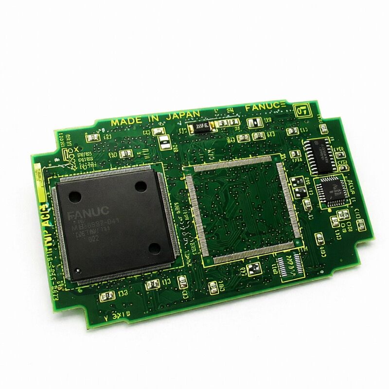
The FANUC A20B-3300-0161 is the CRT Link display control module — the board that sits at the junction between the CNC's processing world and the operator's visual world.
Every parameter value, programme line, tool offset, alarm message, coordinate display, and graphical screen that appears on a FANUC CNC's operator panel passes through this module before reaching the screen. Without it functioning correctly, the operator is effectively blind to the CNC's state — a condition that, depending on the machine type and operation, can range from an inconvenience to a production-stopping failure.
The "CRT Link" designation in the official description reflects the board's architecture. Rather than the CNC main CPU generating the video signal directly, the A20B-3300-0161 receives display data from the main CPU through an internal bus connection (the CRT link interface) and handles all the timing, video signal generation, and display refresh on its own circuits.
This separation is functionally valuable: the display refresh must happen continuously and at precise intervals to maintain a stable, flicker-free image — but these timing requirements conflict with the CNC's own control cycle demands.
A dedicated display module resolves this conflict by giving the display function its own processing resources.
The A20B-3300 family covers FANUC's display module range across multiple CNC generations and display types. Within this family, different variants handle different display configurations: monochrome versus colour, different screen sizes (7.2-inch, 9.5-inch, 10.4-inch), character-only versus graphic capability, and Ethernet-equipped versus non-Ethernet.
The A20B-3300-0161 is a specific variant within this range, identifiable by its cross-reference A350-3300-T166 which also appears in FANUC's parts documentation.
Key Specifications
| Parameter |
Value |
| Function |
CRT Link display control module |
| Cross Reference |
A350-3300-T166 |
| Series |
A20B-3300 |
| Type |
Plug-in display PCB |
| Application |
FANUC CNC operator panel display |
| Origin |
Japan |
What the A20B-3300-0161 Actually Does — The Display Signal Chain
The path from CNC data to what appears on screen involves several processing steps that the A20B-3300-0161 handles:
Character generation: When the CNC needs to display a parameter number, a coordinate value, an alarm message, or a programme line, it sends character codes (ASCII or similar) to the display module. The module contains a character generator ROM that maps these codes to pixel patterns.
Every alphanumeric character and symbol that appears on a character-display CNC screen is rendered by this character generation circuit in the display module.
Graphic rendering (for graphic-capable display modules): For more advanced display variants that support graphical functions — toolpath simulation, waveform display, 3D graphic representations — the display module contains a dedicated graphics processor that renders bitmap graphics from coordinate data sent by the CNC's main CPU.
This graphics processing would consume significant main CPU bandwidth if not offloaded to the display module.
Display timing and synchronisation: CRT displays (and their LCD successors) require precise horizontal and vertical synchronisation signals to maintain a stable image.
The display module generates these timing signals and ensures the video data output is synchronised with them, producing a stable, correctly-framed image regardless of what the CNC's main CPU is doing.
Video signal output: The module converts the digitally-processed display data to the analogue or digital video signal appropriate for the connected display unit — whether a CRT monitor with analogue RGB input or an LCD panel with digital signal input.
Display Module Failure — What It Looks Like and What It Means
The A20B-3300-0161's failure presents in ways that are immediately obvious but sometimes misleading in their implications:
Blank screen: The display backlight (if LCD) or tube high voltage (if CRT) is active — you can detect this by the faint glow or warmth — but nothing appears on screen.
This indicates the display hardware is powered but receiving no valid video signal. Most commonly caused by a failed display module.
Garbled or frozen display: Characters appear in random positions, blocks of the screen show nonsense patterns, or the display is frozen on one image while the CNC is responding to inputs normally (you can hear the spindle, axes moving, etc.).
This suggests the display module is partially functional but its internal circuits have a fault causing incorrect output.
Partial display corruption: Certain areas of the screen are correct (the softkey labels at the bottom, for example) while other areas show scrambled data, or a specific type of display (graphic) is corrupted while character displays are correct.
This is a useful diagnostic indicator: graphic display corruption with correct character display suggests a fault in the graphic processing circuits of the module, not the character generation or basic video output.
Display normal on some screens, blank on others: If the CNC's basic status screens display correctly but switching to the graphic toolpath screen causes the display to go blank, the graphic section of the display module is suspect.
What Does Not Change When the A20B-3300-0161 Is Replaced
A critical point for maintenance planning: the display control module stores no CNC data whatsoever. No machine parameters, no part programmes, no PMC ladder data, no tool offsets — none of this lives in the display module. It is a stateless display processor. Replacing it requires no data backup and no parameter restore.
The only post-replacement action is verifying that the screen displays correctly across the CNC's various screen types.
This is different from replacing a main CPU board or an SRAM module, where comprehensive data backup and restore procedures are mandatory.
A display module replacement is among the cleanest repair operations in FANUC CNC maintenance — swap the board, power up, confirm the display is working.
FAQ
Q1: The CNC axes and spindle work normally but the screen is blank. Does this confirm the A20B-3300-0161 has failed?
A blank screen with otherwise functional CNC axes and spindle is strongly suggestive of a display module failure — but confirm this by checking the display unit's own power supply and cable first.
The display unit (LCD/CRT) has its own power connections; if the display unit's power has failed, the screen will be dark regardless of the display module's health.
If the display unit is confirmed powered (backlight on, inverter active for LCD) but shows no image, the display module is the next suspect.
A quick confirmation is to observe whether the CNC's LED indicators on the main board show normal operation status.
Q2: Can the A20B-3300-0161 be replaced with the adjacent variant A20B-3300-0162?
The -0161 and -0162 are different boards within the A20B-3300 display module family — they handle different display configurations or CNC generations.
They cannot be freely interchanged. The specific module required is determined by the main CPU board it mounts on and the display unit connected to the system.
Consult the CNC's hardware connection manual or match the part number exactly from the installed board's label. Using an incorrect variant will result in a non-functional display even if the board itself is healthy.
Q3: Is there any risk to the CNC's data when replacing the display module?
No. The A20B-3300-0161 stores no machine-specific data. Parameters, programmes, PMC ladder, and offsets all reside in the SRAM and FROM modules on the main CPU board, which are not disturbed by display module replacement.
Power down the CNC completely before removing or installing the display module — this is an ESD and safety precaution — but no data backup is required specifically for this procedure.
Q4: The display shows some correct content (softkeys, page headers) but other parts are scrambled. What does this indicate?
Partial display corruption with some correct content typically indicates a fault in a specific subsection of the display module's circuitry rather than a complete failure.
If the softkey labels at the screen bottom are correct but the main data area is scrambled, the character generator for basic UI elements works but the data display circuitry is faulty.
If the character screens (parameter, offset, programme) are correct but the graphic screen (toolpath, waveform) is corrupted, the graphic rendering subsection has failed.
These symptoms confirm the display module as the fault source and help repair centres diagnose which specific circuit to address.
Q5: How should the A20B-3300-0161 be handled during storage and transit to prevent damage?
The board must be kept in an antistatic bag at all times when not installed — both for storage and during shipping.
Temperature extremes should be avoided: storage below -20°C or above +60°C risks semiconductor damage and solder joint stress from thermal cycling.
The board should not be placed face-down on hard surfaces (component damage), stacked with other boards without antistatic foam between them (contact damage and ESD), or shipped in ordinary cardboard boxes without antistatic packaging (static charge buildup during transport).
A purpose-made antistatic shielding bag inside a rigid cardboard box with foam padding on all sides is the minimum acceptable shipping package.

 Your message must be between 20-3,000 characters!