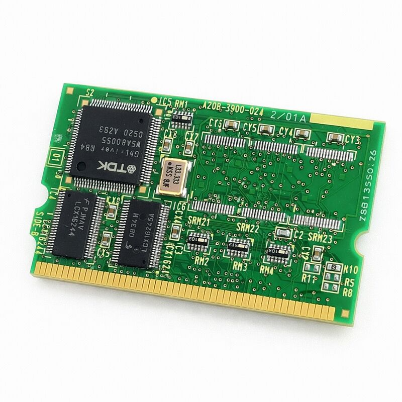
FANUC A20B-3900-0241 | 128 MB FROM / 2 MB SRAM Module B2 — Genuine FANUC, Japan Origin
Part Number: A20B-3900-0241
Manufacturer: FANUC Corporation (Japan)
Product Type: FROM / SRAM Memory Module (PCB)
Designation: Module B2
FROM ID: E4
SRAM ID: 04
Overview
The A20B-3900-0241 is the B2 variant of FANUC's 128 MB FROM / 2 MB SRAM memory module — the counterpart to the B1 (A20B-3900-0240), with the SRAM allocation doubled from 1 MB to 2 MB.
It is confirmed for use in FANUC 0i-D CNC systems, among others, and serves the same fundamental role as every other module in the A20B-3900 series: providing the non-volatile and battery-backed volatile memory the controller depends on to hold its software and runtime data.
128 MB of Flash ROM supports fully loaded FANUC CNC configurations.
System software, servo software, PMC ladder programs, option packages, and user-defined software all reside in FROM.
The FROM on the A20B-3900-0241 stores all of this across power cycles without requiring a battery — Flash ROM is inherently non-volatile.
The controller reads the FROM at power-up and loads its contents into working memory. FROM ID E4 and SRAM ID 04 identify this module's memory configuration within FANUC's diagnostic and configuration systems.
The extra 1 MB of SRAM relative to the B1 variant accommodates applications with larger parameter sets, expanded program storage requirements, or heavier use of FANUC's optional data management functions.
On systems where the B2 was factory-fitted, replacing with a B1 may result in insufficient SRAM for the configured option set.
Key Specifications
| Parameter |
Value |
| Part Number |
A20B-3900-0241 |
| Manufacturer |
FANUC Corporation |
| Product Type |
FROM / SRAM Memory Module (PCB) |
| Designation |
Module B2 |
| Board Series |
A20B-3900 |
| FROM ID |
E4 |
| SRAM ID |
04 |
| FROM Capacity |
128 MB (Flash ROM, non-volatile) |
| SRAM Capacity |
2 MB (battery-backed, volatile) |
| Compatible Systems |
FANUC 0i-D CNC and other FANUC controllers |
| Installation |
Plug-in module, controller main board |
| Post-Installation |
All FROM files, parameters, and programs must be reloaded |
| Origin |
Japan |
| Operating Temperature |
0 – 55°C |
| Storage Temperature |
−20 – 60°C |
| Humidity |
75% RH max (non-condensing) |
| Condition Available |
New / Refurbished / Repaired |
What FROM and SRAM Each Do
Flash ROM does not need a battery. The data it holds stays put regardless of power state. That is the right place for anything that should not change during normal operation: the CNC kernel, the servo control software, the PMC ladder runtime, and application-specific option software. None of these change cycle to cycle.
They load once at power-up and run from RAM until the next power cycle.
SRAM is different. It is volatile — it forgets its contents when power is cut, unless a backup battery keeps it alive.
SRAM holds the data that changes during machine operation: parameters set by the machine operator or service engineer, stored machining programs, active tool data, pitch error compensation tables.
All of this rides in SRAM. The backup battery is a maintenance component — it has a service life and must be replaced periodically before it fails silently.
The 2 MB SRAM on the B2 module matters most in systems that push against the limits of 1 MB.
A controller running a single CNC function with a small program library and a minimal parameter set may never notice the difference.
A controller managing a large machining centre with hundreds of stored programs, an extensive tool life management database, and a full complement of options will find the headroom valuable.
FANUC 0i-D Platform
The FANUC 0i-D is a widely deployed mid-range CNC platform. It powers machining centres, turning centres, wire EDM machines, and grinding machines across a range of axis counts.
The 0i-D brought significant capability improvements over its predecessors — higher axis counts, nano interpolation, improved servo performance, and broader option availability.
Controllers in this generation are still in active production globally, and their FROM/SRAM modules are active maintenance items.
The A20B-3900-0241 is confirmed for 0i-D installations.
The FROM ID E4 and SRAM ID 04 identifiers tie the module to the specific memory configuration the 0i-D platform uses in this capacity range.
These IDs appear in the controller's configuration diagnostics — verifying them after installation confirms the controller has correctly recognised the new module.
Post-Installation Procedure
Replacing the A20B-3900-0241 resets the controller's software and data to a blank state.
Everything that was on the previous module — system software, parameters, programs, compensation data — is gone. It must be restored from backup before the machine can run.
The correct restore sequence: load FROM software first, then parameters, then programs and user data. Attempting to load parameters before the correct software version is installed may produce software mismatch alarms.
Check the software version after FROM installation and confirm it matches the backup's expected version before loading parameters.
Verify the FROM ID and SRAM ID in the controller's diagnostic screen after installation.
E4 and 04 respectively confirm the correct module is recognised.
If the IDs do not appear as expected, investigate the module seating and connector condition before concluding the module is at fault.
FAQ
Q1: After installing the A20B-3900-0241, the controller shows a ROM configuration alarm. What does this mean?
This alarm typically appears when the controller cannot read the FROM correctly, or when the FROM ID does not match the controller's expected configuration.
Confirm the module is fully seated.
If seated correctly and the alarm persists, verify that the module part number is correct for the installed controller type.
The FROM ID E4 should appear in the controller's system configuration diagnostics once the module is correctly recognised.
Q2: Can the A20B-3900-0241 replace the A20B-3900-0240 (B1) in a machine originally fitted with B1?
Generally yes — the B2 provides the same 128 MB FROM as B1, with additional SRAM.
A system originally fitted with B1 will not be harmed by the extra SRAM of the B2.
Confirm with the machine's documentation that the controller model accepts both B1 and B2.
Load all software and parameters as normal after replacement.
Q3: PMC ladder programs are stored on FROM or SRAM?
PMC ladder programs are stored in FROM (non-volatile). They survive power-off without a battery.
However, PMC parameters and some PMC data variables are held in SRAM (battery-backed).
Both FROM and SRAM must be correctly restored after a module replacement for the PMC to function normally.
Reload the ladder through the FROM software restoration procedure, and restore PMC parameters separately.
Q4: The SRAM shows as empty after installation but the FROM loaded correctly. Why?
A new or freshly supplied module has blank SRAM. FROM content was restored through the software load procedure, but SRAM data — parameters and programs — must be loaded separately through the parameter and program restore procedure.
This is a normal, expected step in module replacement. Work through the restore procedure completely before testing machine function.
Q5: How do I confirm the FROM ID and SRAM ID after installing the A20B-3900-0241?
Access the system diagnostics screen on the FANUC controller — typically found under the System / Configuration menu.
The FROM ID and SRAM ID are displayed in the controller's hardware configuration summary.
For the A20B-3900-0241, FROM ID should read E4 and SRAM ID should read 04. These values confirm the controller has correctly identified the installed module.

 Your message must be between 20-3,000 characters!