Backlight Inverter PCB for 0i-C / 0i-D 8.4-Inch Color LCD Systems
Overview
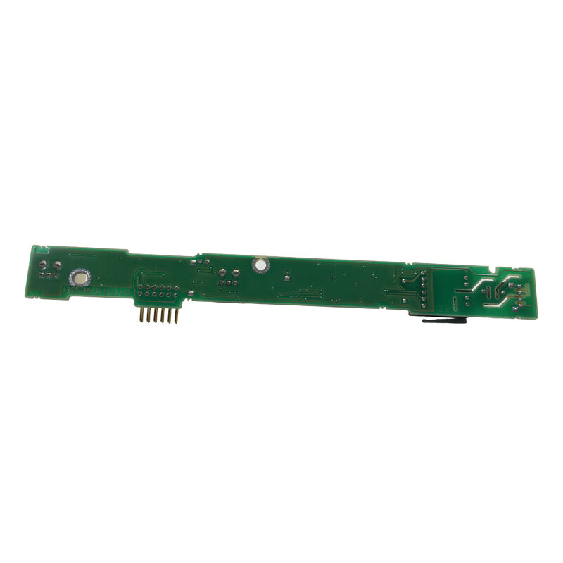
The FANUC A20B-8002-0633 is a backlight inverter PCB used inside 0i-series control systems, especially mid-series 0i-C and 0i-D configurations with 8.4-inch color displays. Its job is to support the power stage required by the LCD backlight section, allowing the screen to illuminate correctly and maintain usable visibility during operation.
In the field, a backlight inverter board is a very specific but very important component.
The LCD panel itself may still be present and technically intact, yet the screen can appear dark, faint, or unreadable if the inverter stage is not functioning properly.
That means a machine may seem to have a failed display when the actual problem is located in the backlight power circuit rather than in the panel or main control board.
This makes the A20B-8002-0633 particularly relevant for repair situations involving dim screens, black display conditions with active control in the background, or inconsistent backlight startup.
For technicians familiar with 0i-series systems, inverter boards are a standard checkpoint in the display power chain, especially in yellow-backed control assemblies where multiple screen-related components work together in a compact structure.
Application Snapshot
Suitable systems
- FANUC 0i-C
- FANUC 0i-D
- Mid-series yellow-backed control assemblies
Associated display size
- 8.4-inch color LCD systems
Board function
- Backlight inverter power support
- LCD illumination circuit role
- Display restoration and maintenance replacement
Why This Board Matters in Service Work
A backlight inverter PCB is not the same as the LCD panel, and it is not the same as the main display control board.
It sits in a more focused electrical role: powering the illumination side of the screen system.
In maintenance practice, this distinction matters because replacing the wrong display component wastes time and does not solve the fault.
The A20B-8002-0633 is therefore best approached as a dedicated service part for restoring brightness and screen readability in the correct 0i-series configuration.
FAQ
Q1: What does the A20B-8002-0633 actually do inside the control?
This board operates as a backlight inverter PCB, meaning it supports the power conversion required for the LCD backlight system. In practical machine terms, it helps the screen light up so the operator can clearly view the CNC interface.
If the inverter section fails, the display may appear black or extremely dim even when the control itself is still running.
Q2: How is an inverter board different from the LCD panel itself?
The LCD panel is the visual display surface, while the inverter board supports the lighting function that makes the panel readable.
A failed inverter can make a healthy LCD appear dead. This is why experienced technicians separate the display problem into panel fault, inverter fault, cable fault, and main-board fault rather than treating every dark screen as a bad LCD.
Q3: What symptoms commonly point to inverter-board failure?
Common symptoms include a very dark screen, a screen that flashes briefly at startup and then goes dim, inconsistent illumination, or a display that becomes unreadable while the control seems otherwise active.
In field diagnosis, technicians often confirm whether the machine is still running in the background before deciding the display issue is backlight-related.
Q4: Why is exact model matching important for backlight inverter boards?
Because inverter boards are tied to specific display sizes, panel configurations, and control families.
A visually similar board may not be electrically appropriate for the target LCD system. In 0i-series controls, correct matching is important not only for fit, but also for stable illumination behavior and long-term reliability.
Q5: What should engineers inspect before replacing this inverter PCB?
They should inspect the LCD panel condition, harnesses, connectors, and surrounding display hardware, and verify that the issue is not caused by upstream power problems or damage in the control cabinet.
It is also good practice to look for signs of heat stress or aging in the display area, since inverter-stage faults are often linked to long operating hours and thermal conditions.

 Your message must be between 20-3,000 characters!