Backlight Inverter PCB for 0i-D B3 9.5-Inch Color Display Systems
Product Introduction
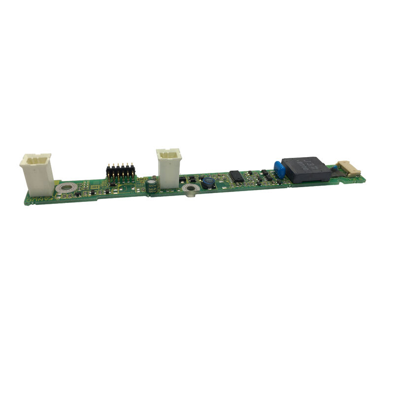
For display-related faults in FANUC 0i-series controls, the A20B-8002-0702 is a targeted and function-specific replacement.
This model is a backlight inverter PCB used in B3 series 0i-D controls with 9.5-inch color displays, where the screen illumination system depends on correct inverter-stage performance.
Unlike a general control card, this board has a focused job within the display assembly.
It helps power the LCD backlight section and supports the readability of the operator screen. When the inverter board becomes unstable, the machine may still be live internally, but the visual interface becomes difficult or impossible to use.
In production settings, that creates a real operational problem because the machine can no longer present alarms, settings, or process information in a normal way.
For parts buyers and maintenance teams, the A20B-8002-0702 is therefore a practical repair component for restoring screen brightness in the correct 0i-D B3 display platform.
It is especially useful where the system architecture is still sound and only the display power stage needs to be corrected.
Technical Positioning
| Parameter |
Value |
| Part Number |
A20B-8002-0702 |
| Brand |
FANUC |
| Board Type |
Backlight Inverter PCB |
| Control Family |
0i-D B3 series |
| Display Size |
9.5 inch color display |
| Main Role |
LCD backlight power support |
| Typical Use |
Repair and replacement |
Service-Oriented Buying Notes
The A20B-8002-0702 is usually purchased by:
- CNC repair providers
- Industrial maintenance departments
- Spare-parts distributors
- Users servicing yellow-backed 0i-D control systems
- Technicians diagnosing dark or dim display faults
Its value is not in being a broad multifunction board, but in solving a very specific category of display-power problem with the correct model.
FAQ
Q1: Which type of FANUC system is this inverter PCB associated with?
The A20B-8002-0702 is associated with 0i-D B3 series controls using 9.5-inch color display assemblies.
In service terms, that makes it a display-support component for a defined control family rather than a universal inverter board.
Accurate system matching is important when identifying the correct replacement.
Q2: Why can a machine appear to have a failed screen when the real issue is the inverter board?
Because the control may still be operating, and the LCD panel may still be present, but without proper backlight power the screen becomes too dark to read.
This can mislead less experienced troubleshooting. Industrial technicians often check whether the CNC is active behind the display issue before concluding that the panel itself is defective.
Q3: Is this board responsible for image processing or just screen lighting?
Its primary role is in the backlight power section rather than the full image-control path.
That distinction is important. Image-generation issues and illumination issues do not always come from the same hardware.
A screen with no readable brightness but otherwise normal control activity often points more strongly to inverter-stage diagnosis than to a main display PCB fault.
Q4: What inspection steps are recommended before replacing this part?
The technician should verify the exact part number, check the display harness, inspect connectors, review cabinet heat conditions, and confirm whether the LCD panel itself has visible damage.
It is also good practice to inspect nearby power-related components, because inverter boards can fail as part of a broader aging process in the screen assembly.
Q5: Why is this part important for continued use of older CNC controls?
Many established CNC systems remain productive long after installation, and display-related faults are among the more common service needs over time.
A correct inverter PCB allows the original screen assembly to remain usable, avoids unnecessary control replacement, and helps keep the machine in service with less disruption to the existing setup.

 Your message must be between 20-3,000 characters!