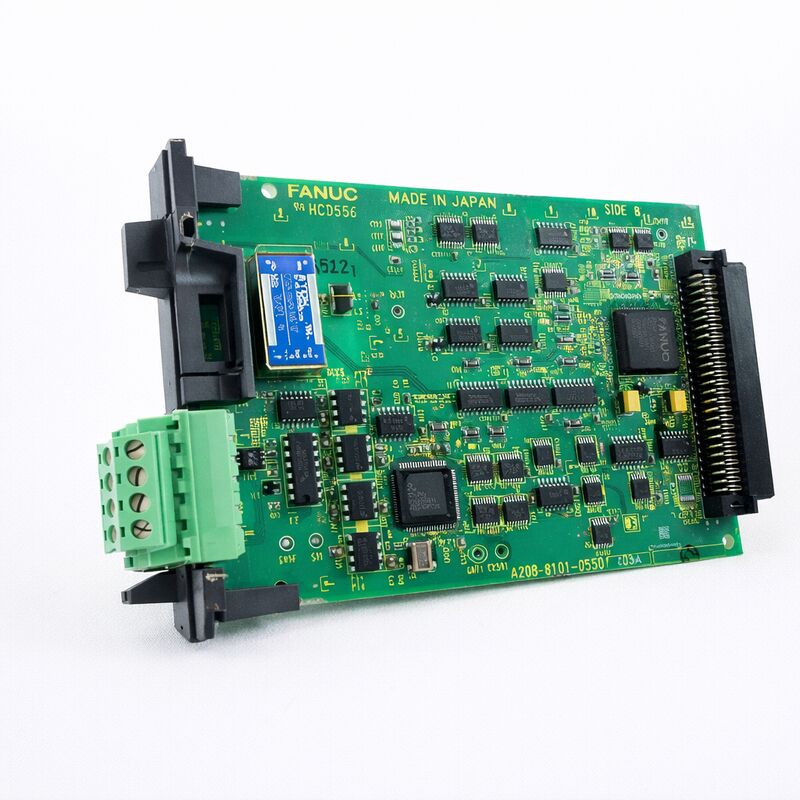
FANUC A20B-8100-0381 | I/O Link II SAVE B PCB — Slave / Master Configurable Fieldbus Board, For Series 16i / 18i / 21i-A & Power Mate i-D/H, A20B-8100 Series, Japan Origin
Part Number: A20B-8100-0381
Manufacturer: FANUC Corporation (Japan)
Product Category: PCB — I/O Link II Option Board (Fieldbus Interface)
Series: A20B-8100 — FANUC i-series option PCB family
Overview
The FANUC A20B-8100-0381 is the I/O Link II interface board — the hardware that adds FANUC's proprietary OPCN-1 (formerly JPCN-1) fieldbus capability to i-series CNC controllers and Power Mate motion controllers.
It enables direct communication between the CNC and a distributed network of I/O modules, drives, and other OPCN-1 certified devices over the I/O Link II bus, independent of the standard I/O Link architecture that most FANUC CNC controllers already include as a built-in function.
I/O Link II is a different and more capable protocol than the original FANUC I/O Link.
The original I/O Link connects the CNC to FANUC's own I/O Unit-A and I/O Unit-B distributed I/O hardware in a master-slave architecture.
I/O Link II is based on the OPCN-1 open fieldbus standard defined by the Japan Electrical Manufacturers' Association, which means I/O Link II-compatible devices extend well beyond FANUC's own I/O hardware to include any OPCN-1 certified products from third-party manufacturers.
This compatibility with OPCN-1 certified equipment expands the range of devices that can be integrated directly into the CNC system's machine control architecture.
The A20B-8100-0381 board serves both the standalone Series 16i/18i/21i-A and the Power Mate i-D/H motion controller platform.
In the Power Mate i-D/H context, this board is specifically designated as the I/O Link-II Slave Board B, reflecting the Power Mate i-D/H's role as a distributed axis controller that functions as a slave on the I/O Link II network managed by a master CNC.
Key Specifications
| Parameter |
Value |
| Compatible CNC |
Series 16i/18i/21i-A (standalone type) |
| Compatible Controller |
Power Mate i-D/H |
| Protocol |
I/O Link II (OPCN-1 / JPCN-1 fieldbus) |
| Configuration |
Configurable master or slave via setting pin SH1 |
| LED Indicators |
4 × green (RUN, COM, SO, SLV); 2 × red (TER, PRT) |
| Connector |
TBA terminal block (OPCN-1 network connection) |
| Installation |
Mini-slot in basic unit (any mini-slot in 1-slot or 3-slot unit) |
| Series |
A20B-8100 |
| Status |
Available — refurbished, tested |
| Origin |
Japan |
I/O Link II — What It Is and Why It Matters
FANUC's original I/O Link connects the CNC to FANUC's own distributed I/O units over a proprietary serial bus. It works reliably within FANUC's own product ecosystem but is limited to FANUC's I/O hardware.
I/O Link II takes a different approach. The protocol is built on OPCN-1, an open fieldbus standard developed by JEMA (Japan Electrical Manufacturers' Association). OPCN-1 certification is a verifiable compliance standard — any device that passes OPCN-1 certification can interoperate with any other certified device on the same network.
This means that on an I/O Link II network, FANUC's CNC can exchange data with OPCN-1 certified I/O terminals, sensors, drives, and other devices from a variety of manufacturers, not just FANUC's own hardware.
For machine builders and system integrators, I/O Link II opens up integration possibilities that the original I/O Link cannot provide. Specialised I/O hardware — safety relays with OPCN-1 certification, valve terminals, sensor blocks — can communicate directly with the CNC over the I/O Link II bus.
The CNC's PMC (Programmable Machine Controller) reads the status of these devices and commands them exactly as it would with native FANUC I/O, with no additional gateway hardware required.
Setting Pin SH1 — Master and Slave Configuration
The A20B-8100-0381 board carries a setting pin (SH1) that determines whether the board operates as an I/O Link II master or slave. This is an important configuration point:
Slave mode: The CNC's main I/O Link II board acts as a slave to a master station.
When the board is installed in a Power Mate i-D/H controller, it is always configured as a slave (the Power Mate acts as a distributed slave axis controller on the I/O Link II network of a higher-level master CNC).
The plug is installed on the SLAVE side and must not be moved in the Power Mate i-D/H application.
Master mode: When installed in a standalone 16i/18i/21i-A controller for the master station function — where the CNC is the master of the I/O Link II network and OPCN-1 slave devices are connected to it — the setting pin is moved to the MASTER side.
The setting pin position must be correct for the specific application.
An incorrect setting causes I/O Link II communication failures that appear as network alarms on the CNC.
Status LED Diagnostics
The A20B-8100-0381 provides six status LEDs — four green and two red — that display the board's operational state in real time:
Green LEDs:
- RUN — Board is powered and the processor is executing normally.
- COM — I/O Link II communications are active.
- SO — Status output; reflects the network communication state.
- SLV — Slave status indicator (illuminated when operating in slave mode with valid network communication).
Red LEDs:
- TER — Terminal error; indicates an issue with the board's TBA terminal block connections.
- PRT — Protocol error; a network-level communication fault on the I/O Link II bus.
During commissioning, monitoring these LEDs confirms that the board has established communication with all configured I/O Link II slave devices.
During troubleshooting, the pattern of illuminated and extinguished LEDs narrows the fault location to the board, the network wiring, or a specific connected device.
FAQ
Q1: What is the difference between the I/O Link II board (A20B-8100-0381) and the standard I/O Link interface built into most FANUC CNC main boards?
The standard I/O Link (JD44A or similar connector on the main board) communicates with FANUC's I/O Unit-A and I/O Unit-B distributed I/O hardware. I/O Link II, enabled by the A20B-8100-0381, uses the OPCN-1 open fieldbus protocol, which is compatible with any OPCN-1 certified device including hardware from non-FANUC manufacturers.
The two systems operate independently — a CNC can use both simultaneously, with the standard I/O Link serving FANUC I/O units and I/O Link II serving OPCN-1 devices on a separate network.
Q2: The PRT (protocol error) LED is illuminated on the A20B-8100-0381. What does this indicate and how should it be diagnosed?
The PRT LED indicates a protocol-level error on the I/O Link II network — the board is not communicating correctly with devices on the bus.
First, verify the TBA terminal block wiring against the FANUC I/O Link II connection manual: check the terminating resistor at the last device in the chain, confirm correct signal polarity, and verify cable shield connections.
Next, confirm all connected devices are OPCN-1 certified and powered.
If individual devices were recently added, confirm the CNC's I/O Link II configuration parameters reflect the current network device count and address assignments.
Q3: Can the A20B-8100-0381 be installed in any of the option slots in a 16i/18i/21i-A CNC basic unit?
Yes. For the standalone Series 16i/18i/21i-A, the I/O Link II board can be installed in any mini-slot of the 1-slot or 3-slot basic unit.
Unlike the data server board, which has specific slot restrictions, the A20B-8100-0381 has no positional constraint relative to the LCD or other boards.
Confirm the specific unit's available slot configuration before installation.
Q4: The setting pin SH1 is installed on the SLAVE side. Can it be moved to the MASTER side in the field?
Yes, for a 16i/18i/21i-A controller where master mode is required. Move the plug from the SLAVE side to the MASTER side.
However, the Power Mate i-D/H application requires the slave side setting and the FANUC documentation explicitly states: "Do not change the setting" in this context.
Before moving the pin, verify the intended operating role of the controller. Power down the system before changing the setting pin position.
Q5: What OPCN-1 certified devices can be connected to the A20B-8100-0381 I/O Link II network?
Any device that has passed OPCN-1 (JPCN-1) certification from JEMA can be connected. This includes FANUC's own I/O Link II slave I/O units, as well as third-party OPCN-1 certified products such as distributed I/O terminals, valve manifolds, smart sensors, and certain drive systems that carry this certification.
The number of connected devices and the total data volume are governed by the I/O Link II specifications.
Consult the FANUC I/O Link II connection manual for network size limits and device configuration procedures.

 Your message must be between 20-3,000 characters!