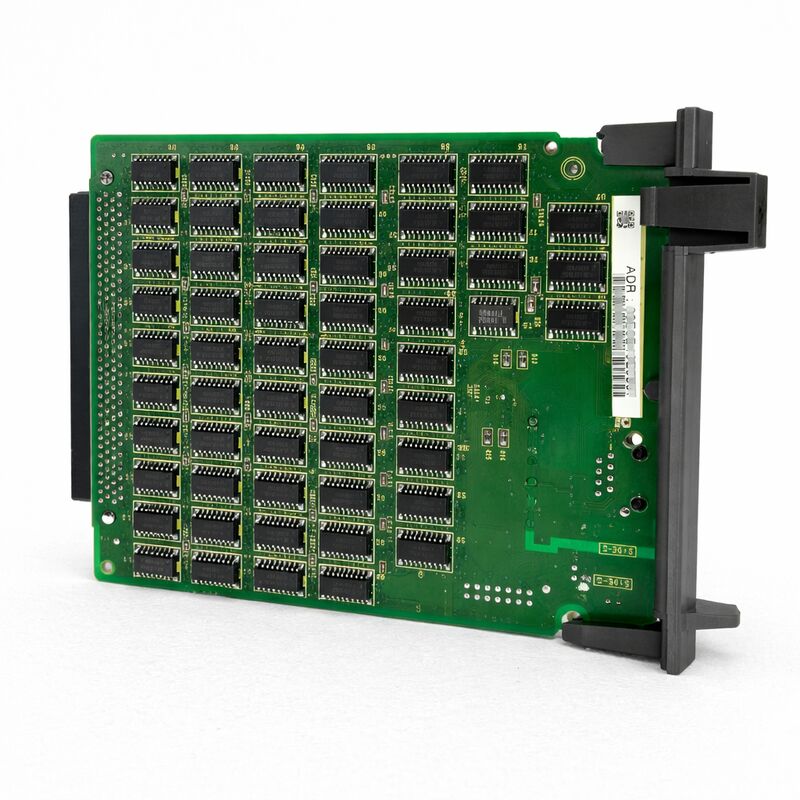
FANUC A20B-8100-0530 | FL-NET PCB — Factory LAN Ethernet Fieldbus Interface Board, For Series 16i / 18i / 21i Model A CNC, A20B-8100 Series, Japan Origin
Part Number: A20B-8100-0530
Manufacturer: FANUC Corporation (Japan)
Product Category: PCB — FL-net Option Board (Factory LAN Ethernet Fieldbus Interface)
Series: A20B-8100 — FANUC i-series option PCB family
Overview
The FANUC A20B-8100-0530 is the FL-net (Factory LAN) interface board for FANUC Series 16i/18i/21i Model A CNC controllers.
It installs in an option slot of the i-series CNC basic unit and adds FL-net Ethernet fieldbus capability to the controller — enabling the CNC to participate as an equal peer node on a factory-wide FL-net network connecting CNC machines, PLCs, and other FL-net compatible devices.
FL-net is the factory-floor network standard developed by the Japan Electrical Manufacturers' Association under the OPCN-2 specification.
Unlike general-purpose industrial Ethernet protocols, FL-net was designed specifically for real-time deterministic communication between factory automation controllers.
The protocol uses a cyclic communication model where all nodes on the network share data areas — each node writes to its own defined area and reads from the areas of other nodes — in a predictable, time-bounded cycle. This cycle behaviour makes FL-net suitable for applications where two or more controllers need to exchange I/O status, operational data, and synchronisation signals with guaranteed timing.
The A20B-8100-0530 connects to the factory's FL-net Ethernet infrastructure through the CD38N connector on the board's edge.
The board communicates with the CNC's internal bus through the F-BUS backplane interface.
From the CNC's PMC perspective, FL-net data appears in a defined memory area that the PMC ladder programme can read and write — the network communication is handled entirely by the board, transparently to the PMC application logic.
Key Specifications
| Parameter |
Value |
| Compatible CNC |
FANUC Series 16i / 18i / 21i — Model A |
| Protocol |
FL-net (OPCN-2 factory LAN Ethernet fieldbus) |
| Network Connector |
CD38N (FL-net Ethernet) |
| Backplane Interface |
F-BUS (CNC internal bus) |
| Board Type |
Option PCB (installs in option slot) |
| Series |
A20B-8100 |
| Status |
Available — refurbished, tested |
| Origin |
Japan |
FL-net — The Factory-Floor Ethernet Standard
FL-net takes a fundamentally different approach to Ethernet-based factory communication compared to FANUC's other network options. To understand why, it helps to contrast FL-net with the two other Ethernet-related boards in the same i-series option family:
Fast Ethernet board (A20B-8100-0670 or A20B-8101-0030): Provides DNC/FTP programme transfer and FOCAS2 monitoring via standard Ethernet.
The CNC acts as a network-connected device that responds to requests from a host computer.
Communication is event-driven and asymmetric — the host asks, the CNC responds. This is ideal for DNC programme management and monitoring applications.
FL-net board (A20B-8100-0530): Provides peer-to-peer cyclic data sharing between controllers.
All nodes share data areas in a defined cycle. No host computer is needed to initiate communication. The CNC and PLC exchange I/O data continuously and deterministically.
This is ideal for inter-controller coordination — for example, synchronising two CNC machines in a transfer line, or passing cell-level status signals between a robot controller and a CNC.
FL-net was specifically designed for factory automation applications where controllers need to share data with each other rather than with a central computer. Its cyclic communication model guarantees that all nodes have current data from all other nodes within each network cycle, which is exactly the behaviour needed for coordinated production cell control.
F-BUS Integration and PMC Data Mapping
When the A20B-8100-0530 is installed, FL-net data is mapped into the CNC's memory areas in a way that makes it directly accessible to the PMC ladder programme.
The FL-net board manages the network communication cycle — receiving data from other nodes on the FL-net network and updating the PMC-accessible memory area, and writing PMC-commanded output data back onto the network in each cycle.
From the PMC ladder's perspective, reading FL-net inputs from another controller's output area is as simple as reading any other I/O signal.
The machine builder programs the PMC to read and write the FL-net memory areas that have been assigned to this CNC's node address.
The PMC does not need to manage network timing, protocol handling, or node addressing — all of that is handled by the A20B-8100-0530 board.
This transparency makes FL-net particularly attractive for machine builders who want to add inter-machine communication without modifying the structure of the PMC programme beyond adding the relevant memory read/write instructions for the new data areas.
Applications
The A20B-8100-0530 addresses specific production automation scenarios:
Transfer line coordination. Multiple CNC machines in a production transfer line use FL-net to share handshake signals, part-ready status, emergency stop propagation, and cycle state information.
Each machine knows the state of adjacent machines in real time, enabling coordinated production flow without a central PLC intermediary.
CNC–PLC integration. A PLC managing conveyor, fixture clamping, and material handling communicates with the CNC over FL-net, exchanging part arrival signals, clamp confirm, and cycle complete data. Both controllers see each other's status in every FL-net cycle.
Cell-level monitoring. An FL-net connected monitoring system collects operational data — spindle load, feed rates, alarm status — from multiple CNC nodes on the same factory-floor network without requiring separate DNC connections to each machine.
FAQ
Q1: Can the A20B-8100-0530 FL-net board and the Fast Ethernet board both be installed in the same 16i/18i/21i-A CNC simultaneously?
Yes, if the CNC's basic unit has enough available option slots. The FL-net board and the Fast Ethernet board use different network ports and serve different functions — FL-net for inter-controller cyclic data sharing, Fast Ethernet for DNC programme transfer and FOCAS2 monitoring.
Both can be present and active simultaneously, each in its own option slot, with the CNC using both network functions concurrently.
Q2: An alarm related to FL-net communication appears at CNC startup. What is the first diagnostic step?
Confirm the FL-net network cable is connected to the CD38N connector and the network is active.
FL-net requires all nodes to complete their initialisation sequence before the cyclic communication phase begins — if even one node fails to join, the network cycle may not start correctly.
Check the FL-net status display (if available on the CNC's operator panel) to see which nodes are active.
If the CNC node itself is not appearing in the network, verify the node address parameter setting and confirm it is unique within the network.
Q3: How many CNC nodes can participate in one FL-net network?
The FL-net (OPCN-2) standard supports up to 254 nodes per network segment.
In practice, production installations typically use far fewer — a typical machine cell with 5–20 CNC and PLC nodes is common.
The cycle time of the FL-net communication increases with the number of nodes and the volume of data being shared.
For time-critical applications, confirm that the cycle time with the planned node count and data volume meets the application's timing requirements.
Q4: After the A20B-8100-0530 is installed, what parameter settings are required in the CNC to activate FL-net communication?
At minimum, the CNC's FL-net parameters must be configured with: the local node address (a unique number on the network), the data area assignments (which memory addresses map to which node areas), and the FL-net option enable bit.
The specific parameter numbers are documented in the 16i/18i/21i-A FL-net connection manual. Machine builders building an FL-net system from scratch also need to configure the network's total node count and cycle timing parameters.
Q5: The FL-net board is installed but the PMC cannot read data from another controller on the network. The LED indicators on the board appear normal. What should be investigated?
Normal LED status with no PMC data exchange usually indicates a parameter configuration issue rather than a hardware fault. Check:
(1) the memory area assignment parameters — confirm the remote node's data area is correctly mapped to a PMC-accessible address range;
(2) the remote node's FL-net parameters — the sending node must be configured to write its data to the same area that the receiving node is reading;
(3) the FL-net status screen on the CNC — confirm both nodes are listed as active participants in the current network cycle.
If the PMC programme was not modified to include FL-net read/write instructions, the data area exists in memory but the ladder never accesses it.

 Your message must be between 20-3,000 characters!