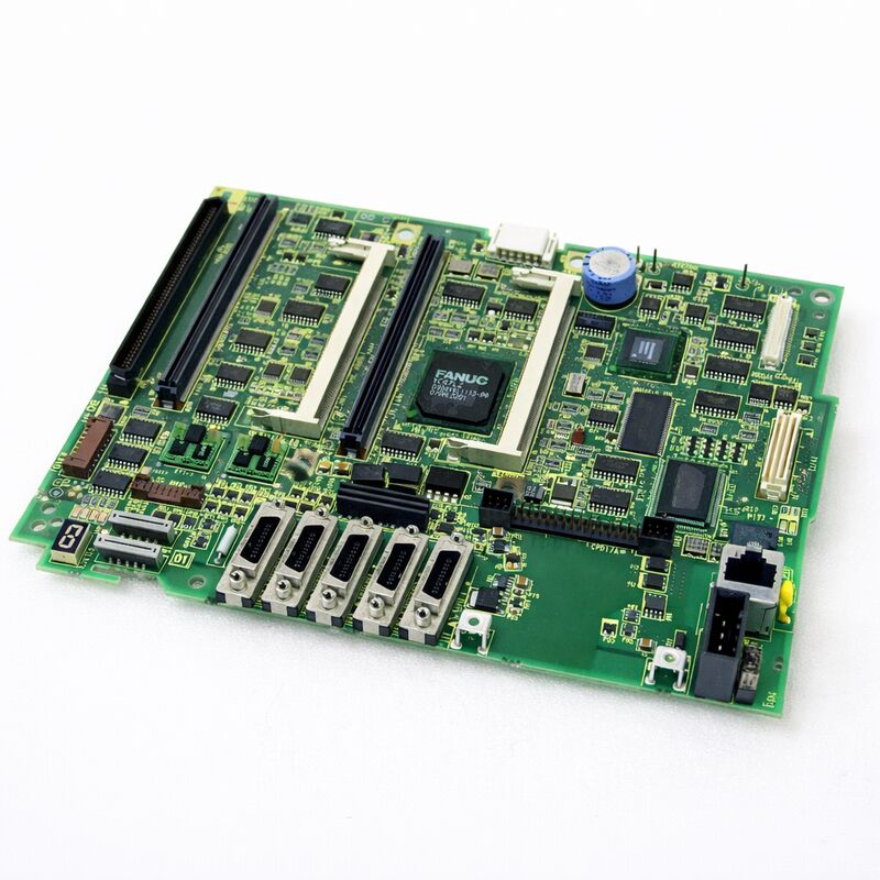
FANUC A20B-8101-0375 | Main PCB G5 — 310i-SA / 320i-SA PANEL i Standalone Type CNC Controller, A20B-8101 Series, Japan Origin
Key Specifications
| Parameter |
Value |
| Compatible CNC |
FANUC 310i-SA (31i-A5), 320i-SA (32i-A) |
| Configuration Type |
Standalone (PANEL i — separate control cabinet) |
| Hardware Generation |
G5 |
| Series Family |
A20B-8101 |
| Companion PSU |
A20B-8101-0010 series |
| SRAM Backup |
Required before replacement |
| Status |
Available — refurbished, tested |
| Origin |
Japan |
Overview
The FANUC A20B-8101-0375 is the G5-generation master board for the 310i-SA and 320i-SA controllers.
These are the standalone-type variants of FANUC's high-end i-series family — the same computational power as the LCD-mounted 31i/32i-A, but packaged in a configuration where the control electronics live in a dedicated rack cabinet rather than behind the operator panel.
The standalone architecture makes sense for large machine tools. Heavy machining centres, gear-cutting machines, and multi-pallet automation lines often have control cabinets mounted remotely from the operator position — away from coolant, vibration, and the physical constraints of panel mounting.
The 310i-SA / 320i-SA puts the main board and all associated electronics in that remote cabinet, connecting to the PANEL i display and MDI unit via an optical fibre link.
The G5 designation marks a hardware revision step. FANUC releases new board generations when component improvements or reliability updates justify a new PCB design.
The G5 replaces earlier generations for the 310i-SA / 320i-SA family. In practice, the G5 board performs the same functions as its predecessors and serves as the replacement for earlier-generation main boards in the same CNC family.
Standalone vs LCD-Mounted Architecture
Understanding the SA (Standalone) architecture helps clarify what makes this board different from LCD-mounted type main boards like the A20B-8101-0401.
In an LCD-mounted type 30i/31i/32i-A, the main board sits directly on the back of the operator panel.
The control electronics and display are physically integrated at the machine's operator station. This is compact and works well for smaller machines.
In a standalone (SA / PANEL i) type, the main board lives in a separate control rack.
The PANEL i display and MDI keyboard are at the operator station — but they contain only display and input electronics, connected to the remote main board via high-speed fibre-optic cables.
This separation offers:
- Full physical isolation of the control electronics from the machining environment
- Freedom to mount the operator panel in the optimal position for the operator
- Easier access to the control rack for maintenance
- Cleaner EMC separation between the power-heavy drive electronics and the CNC's main board
For machines with multiple operator stations, the standalone architecture also allows a single controller to serve more complex operator panel arrangements.
G5 Board Generation — What Changes Between Revisions
FANUC's hardware revision numbering (G1, G3, G5…) tracks incremental hardware improvements to the same functional design. Between revisions, FANUC typically updates component specifications, transitions to newer ICs, improves thermal management, or corrects minor issues identified in the field.
The function of the board does not change — the G5 performs identically to the G3 from the CNC software's perspective.
From a maintenance standpoint, the G5 is the appropriate replacement for earlier hardware generations in the 310i-SA / 320i-SA family.
When ordering a replacement, specifying the G5 (A20B-8101-0375) ensures compatibility with current FANUC parts support, since earlier generations may no longer be available and the G5 is designed to serve as the cross-generation replacement.
Replacement Procedure Overview
Replacing the A20B-8101-0375 in a standalone 310i-SA / 320i-SA system requires careful attention to the standalone cabinet layout:
Step 1 — Data backup. Before touching the board, perform a complete SRAM backup via the CNC boot screen. Save to a FANUC memory card or PC via RS-232C. Capture all programmes, parameters, and PMC data.
Step 2 — Power isolation. Shut down the machine fully. Confirm the control rack's DC bus has discharged. De-energise and lock out the control cabinet.
Step 3 — Cable documentation. In a standalone cabinet, more cables connect to the main board than in an LCD-mounted configuration. Photograph all cable connections before disconnecting. Label each cable.
Step 4 — Board swap. Remove plug-in modules (CPU card, memory modules, servo control card) from the original board and transfer them to the replacement board. Seat each module carefully.
Step 5 — Reconnection. Reconnect all cables following the documentation from Step 3. Reconnect the fibre-optic PANEL i link.
Step 6 — SRAM restore. Power up in boot mode. Load the SRAM backup. Confirm all data loaded correctly before entering normal operation.
FAQ
Q1: The 310i-SA controller shows "9001" system alarm after the A20B-8101-0375 was replaced. What is the likely cause?
A 9001 alarm immediately after board replacement usually indicates a configuration mismatch between the new board and the loaded SRAM data, or the SRAM restore did not complete correctly.
First, confirm all plug-in modules are properly seated — a partially inserted servo card or CPU card triggers configuration alarms. Second, retry the SRAM restore from boot mode.
If the alarm persists, the board revision may require a specific software parameter to recognise the G5 hardware correctly — consult the FANUC maintenance manual or contact FANUC service for the specific board initialisation procedure.
Q2: Can the G5 board (A20B-8101-0375) replace a G3 board (A20B-8101-0373) in the same machine?
Yes. The G5 is FANUC's intended replacement for earlier generation main boards in the 310i-SA / 320i-SA family.
The hardware generation does not change the CNC software's operation. All plug-in modules from the original G3 board (CPU card, servo card, memory modules) transfer to the G5 board and continue to operate correctly.
The SRAM data backup and restore procedure is the same regardless of which hardware generation is being installed.
Q3: The PANEL i display shows a "link error" after the standalone cabinet main board was replaced. What should be checked?
A PANEL i link error after main board replacement almost always points to the fibre-optic cable connection between the standalone cabinet and the PANEL i display unit. During the board replacement, the fibre-optic connectors may have been disturbed or the cable pulled tight.
Check both ends of each fibre-optic cable — at the main board's COP connector and at the PANEL i unit's receive connector.
Clean the fibre ends with a lint-free wipe if any contamination is visible.
Reconnect firmly and verify the link status indicator (if fitted) shows normal.
Q4: How is the standalone type 310i-SA different from a network-connected (Panel i) display unit for maintenance purposes?
The main board (A20B-8101-0375) in the standalone cabinet generates all CNC processing. The PANEL i display unit at the operator station contains only display electronics and an MDI keyboard — it has no CNC processing capability of its own.
For maintenance, this means all diagnostic data (alarm logs, parameter readback, ladder monitoring) is available through the PANEL i display even though the processing happens remotely.
If the display shows no image, the fault can be in the fibre link, the PANEL i display unit itself, or the display output circuits of the main board.
Q5: Should the SRAM battery be replaced at the same time as the main board?
If the machine's SRAM backup battery is more than 2 years old or the battery alarm was active before the board failure, replace the battery during the main board swap. The SRAM backup battery maintains machine data (parameters, PMC ladder, programmes) when the controller is powered down.
After installing a new main board, load the SRAM data from the backup medium.
Once confirmed, installing a fresh battery ensures the data is reliably maintained during future power-off periods.
Always replace the battery with the CNC powered ON to avoid losing SRAM data.

 Your message must be between 20-3,000 characters!