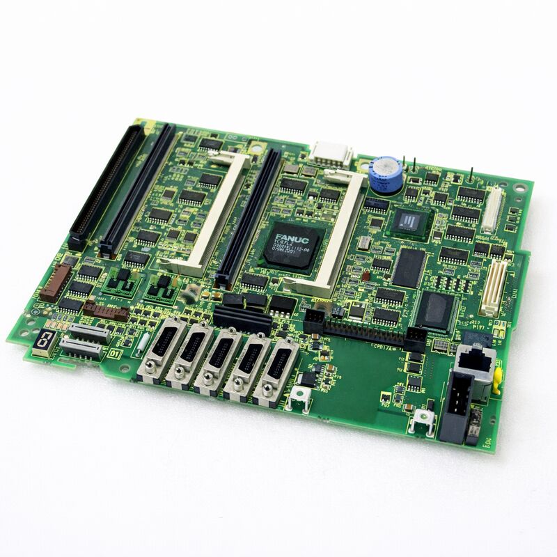
FANUC A20B-8101-0401 | Main PCB A5 for Series 30i/31i/32i-A — Without PC Function, LCD/MDI Unit Mount, Japan Origin
Overview
The FANUC A20B-8101-0401 is the master board for one of FANUC's most capable CNC generations. The Series 30i/31i/32i-A represents the high-performance tier of FANUC's i-series — controllers built for complex, multi-path, multi-axis machines. Five-axis machining centres.
Compound turning centres. Gear-grinding machines. Multi-pallet FMS lines. These are the machines where the 30i/31i/32i family lives.
The A5 designation refers to this board's hardware revision within the Series 30i/31i/32i-A product lifecycle.
It succeeds earlier main board variants and incorporates FANUC's hardware updates to address reliability and compatibility requirements that accumulated during the field deployment of earlier versions.
When FANUC releases an updated main board variant like A5, it typically becomes the replacement for all earlier variants — so the A20B-8101-0401 serves not only as a like-for-like replacement for its exact hardware generation but also as the appropriate replacement for earlier main board versions in the 30i/31i/32i-A family.
The "without PC function" specification is an important procurement detail.
The 30i/31i/32i series was offered in two configurations: standard (without integrated PC) and with integrated PC function.
The PC-function variant runs a Windows-based embedded PC on the same main board, enabling FANUC's open CNC functions, custom HMI development, and PC-based application software.
The A20B-8101-0401 is the non-PC variant. It is not interchangeable with the PC-function main board — the hardware, connectors, and software configuration differ between the two.
Key Specifications
| Parameter |
Value |
| Compatible CNC |
FANUC Series 30i-A, 31i-A, 32i-A (30i-TA, 30i-MA) |
| PC Function |
Not included |
| Mounting Location |
LCD/MDI unit (operator panel) |
| Companion PSU |
A20B-8101-0010 |
| Hardware Revision |
A5 |
| Module Interface |
FSSB, Serial Spindle, I/O Link |
| Plug-in Modules |
CPU card, FROM/SRAM, axis control card |
| Pre-Replacement Step |
SRAM data backup mandatory |
| Status |
Available — refurbished, tested |
| Origin |
Japan |
LCD/MDI Mounting — Why It Matters
The Series 30i/31i/32i-A uses a different physical architecture from earlier FANUC i-series controllers. In Series 16i/18i, the main board lives inside the control cabinet on a rack. In the 30i/31i/32i-A, the main board is mounted directly on the back of the LCD/MDI unit — the operator panel.
This integration shrinks the overall cabinet footprint and simplifies cabling, but it changes the maintenance procedure.
To access the A20B-8101-0401, the operator panel must be opened or the LCD/MDI unit must be removed from the machine.
The board is accessible from the rear of the panel. This means replacement can often be done at the machine without completely dismantling the control cabinet.
However, the LCD/MDI unit's mounting location — sometimes high on the machine, sometimes in a pendant — means access conditions vary significantly between machine designs.
Plan the access before starting. Confirm what tools are needed. Confirm the replacement board is tested and ready.
The SRAM backup and reload is the most time-consuming part of the procedure — the physical board swap itself, once access is established, is straightforward.
SRAM Data — The Critical Backup Step
The A20B-8101-0401 interfaces with FROM/SRAM modules that hold all machine-specific data.
This includes CNC parameters, PMC (Programmable Machine Controller) ladder programme, tool offset data, work coordinate systems, and stored part programmes.
None of this data is on the main board itself — it is on the FROM/SRAM modules.
However, some controller configurations store boot-related data in SRAM that must be managed carefully during board replacement. FANUC's maintenance guidance is clear:
back up all SRAM data before starting. Use FANUC's boot screen backup function, DNC transfer, or a FANUC memory card to capture the full data set. After replacing the board, restore the SRAM data before attempting normal operation.
Skipping this step creates a situation where the machine cannot run — parameters are at default values, the PMC has no ladder to execute, and part programmes are gone.
Recovery from this is possible but time-consuming. Five minutes of backup before starting the work saves potentially hours of re-entry after.
FAQ
Q1: After replacing the A20B-8101-0401, the CNC shows alarm "SR" or memory-related startup errors. What does this mean?
SR alarms at startup typically indicate that the SRAM data was not correctly restored after board replacement. Check that the SRAM backup was loaded completely. If the backup process was interrupted or the wrong data file was used, the CNC will start with corrupted or incomplete parameter data.
Use FANUC's boot menu to reload the SRAM image from the backup media. If no backup was taken before the replacement, contact FANUC or a certified engineer — recovering default parameters is possible but requires careful manual re-entry of all machine-specific values.
Q2: Can the A20B-8101-0401 replace the earlier A20B-8101-0400 main board in a Series 30i/31i-A CNC?
Yes. The -0401 (A5 revision) is the updated replacement for the -0400 and earlier main board variants in the 30i/31i/32i-A non-PC family.
FANUC designates new hardware revisions as the replacement for all preceding variants, so the -0401 is appropriate for any 30i/31i/32i-A machine that used an earlier non-PC main board.
Confirm the machine uses the non-PC configuration before ordering — the PC-function board variants have different part numbers and are not interchangeable.
Q3: The machine uses a 15-inch color LCD panel. Does the A20B-8101-0401 support this display?
The A20B-8101-0401 main board connects to the LCD unit through the display interface integrated into the LCD/MDI assembly.
Board compatibility with display size is typically determined by the overall CNC system configuration rather than the main board alone.
If the original main board worked with the 15-inch color panel, a direct replacement with the A20B-8101-0401 will also work with that panel.
If in doubt, verify the display interface specification matches between the replacement board and the installed LCD unit.
Q4: How long does a full A20B-8101-0401 replacement procedure typically take?
For a technician experienced with 30i/31i/32i-A hardware, the complete procedure — SRAM backup, physical board swap, SRAM restore, and functional verification — typically takes 2 to 4 hours. The physical swap itself takes 30 to 60 minutes depending on panel access.
SRAM backup and restore, including verification, accounts for much of the remaining time.
First-time procedures on an unfamiliar machine configuration take longer. Having the FANUC maintenance manual for the specific machine open and available speeds up the process significantly.
Q5: The CNC produces a "SYSTEM ALARM" at power-up after the new A20B-8101-0401 was installed. The display shows an error code. How should this be investigated?
A system alarm immediately after board installation usually indicates one of three things: an incomplete SRAM data restore, a hardware configuration mismatch (such as a CPU card or FROM/SRAM module not properly seated), or a physical connection issue (a cable not fully reconnected during reinstallation).
Check all module seating first — press each plug-in module firmly into its connector. Verify all cables are reconnected. Then attempt the SRAM restore from the boot menu.
If the alarm persists after these checks, record the specific error code and cross-reference it in the FANUC Series 30i/31i/32i-A Maintenance Manual (B-63945EN).

 Your message must be between 20-3,000 characters!