FANUC A20B-8101-0440 | Main Control PCB — A20B-8101 High-End CNC Series, Industrial CNC Control Board, Japan Origin
Overview
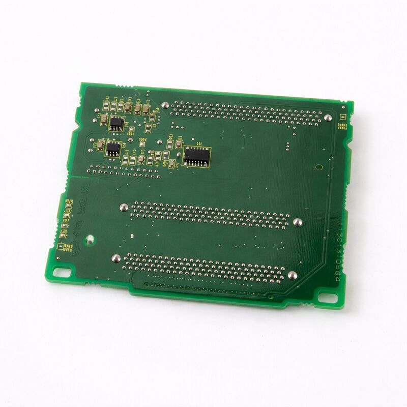
The FANUC A20B-8101-0440 belongs to one of the most technically capable board families FANUC has produced — the A20B-8101 series for the 30i/31i/32i CNC generation.
This is the board family for machines that push the limits of what CNC machining can do: five-axis simultaneous cutting on aerospace components, multi-path turning and milling on compound machine centres, nano-interpolation on optical-grade surfaces, and synchronised multi-spindle operations on transfer lines.
Every function the CNC performs runs through the hardware in the A20B-8101 series.
The main board's processor handles interpolation calculations, servo communication, spindle interface, and PMC ladder execution simultaneously, all within cycle times that keep the machine running at commanded feed rates without interruption.
The board's communication circuits — FSSB for servo amplifiers, I/O Link for machine I/O, serial spindle links for spindle drives — handle dozens of simultaneous high-speed data exchanges every millisecond.
The A20B-8101-0440 represents this level of control hardware.
Like all boards in the family, it operates in the demanding environment of a production machine tool: thermal cycling as the machine warms up and cools down, vibration from the machining process transmitted through the machine structure, and the electrical environment of a cabinet shared with high-power servo drives and spindle amplifiers.
FANUC designs these boards for this environment — industrial-grade components, careful PCB layout for EMC immunity, and connector systems rated for the mechanical demands of production use.
Key Specifications
| Parameter |
Value |
| Series |
A20B-8101 |
| Compatible Platform |
FANUC Series 30i/31i/32i-A and variants |
| Category |
Main / high-function CNC control PCB |
| Operating Voltage |
System-supplied (CNC control rack) |
| Construction |
Industrial FR-4 PCB, SMD components |
| Interface |
FSSB, I/O Link, Serial Spindle, Display |
| Status |
Available — refurbished, tested |
| Origin |
Japan |
A20B-8101 Family Architecture
The A20B-8101 series is large and covers many distinct functions. Understanding where the -0440 fits requires a brief look at the family structure.
The lowest-numbered boards in the family (A20B-8101-0010 through roughly -0100) cover option and communication boards: the -0030 is the Fast Ethernet board, the -0050 is the Profibus master, the -0100 is the Profibus slave, the -0220 is the DeviceNet master, the -0330 is the DeviceNet slave.
These are option boards that plug into the main board's expansion slots to add communication capabilities.
Higher-numbered boards include the main CPU boards for various 30i/31i/32i-A hardware generations and configurations: -0360 through -0403 cover the main board range including the SA (standalone) and non-SA variants.
Beyond these, boards in the -0440 and higher range cover later-generation variants and specialised configurations within the 30i/31i/32i-A family.
All boards in the family share the same design principles: industrial robustness, FANUC's proprietary bus architecture, and software compatibility with the 30i/31i/32i-A CNC software.
Maintenance Priorities for A20B-8101 Series Boards
Maintaining boards in the A20B-8101 family requires the same disciplined approach across all variants:
Pre-work data protection. All SRAM data — parameters, PMC ladder, programmes, coordinate data — must be backed up before any main board is removed.
The FROM/SRAM modules may be on or separate from the main board, but the backup process is identical: use FANUC boot screen backup function or DNC transfer to a PC.
Module management. Plug-in modules installed on the original board (CPU card, servo control card, memory modules) transfer to the replacement board. Each module must be seated fully — incomplete seating causes fault patterns that mimic main board failure.
Connection integrity. After reinstallation, verify all cables are fully engaged. The FSSB fibre-optic connectors are particularly important — a fibre that appears connected but is not fully locked produces intermittent servo communication errors that are difficult to diagnose without knowing the fibre was disturbed.
Systematic verification. After data restore and power-up, navigate all CNC display screens, verify PMC operation through machine I/O test, confirm servo axis readiness, and run a test cycle on a known programme before releasing the machine to production.
FAQ
Q1: How do I confirm the A20B-8101-0440 is the correct replacement board before ordering?
Cross-reference the part number against the machine's electrical documentation or the existing main board's label. FANUC main boards have their part number printed on the board itself, often with a suffix indicating the hardware revision.
Confirm the board's part number matches the replacement being ordered, including any suffix. If the machine's original part number is no longer available, contact a FANUC-specialist parts supplier to confirm which current boards are compatible replacements.
Q2: After installing the A20B-8101-0440, the CNC boots but the servo axes show alarm 401 (servo ready off). What does this indicate?
Alarm 401 (VRDY OFF) at startup after board replacement typically indicates the FSSB fibre-optic connection between the main board and the first servo amplifier in the FSSB chain has not been established. Check the COP10A connector on the board — confirm the fibre-optic cable is fully inserted and latched.
Also confirm the servo amplifiers are powered (24V control power applied) before the CNC attempts FSSB communication.
If the FSSB topology has multiple amplifiers, the CNC must communicate with each in sequence — a fault at one amplifier breaks the chain downstream.
Q3: The machine has a PC-function option (Windows-based open CNC). Does the A20B-8101-0440 support this?
PC-function capability in the 30i/31i/32i-A generation is tied to specific main board variants. PC-function boards include an embedded PC subsystem (processor, memory, and PC-side interfaces) in addition to the standard CNC main board functions.
Standard (non-PC) boards lack this subsystem. Before ordering, confirm whether the machine's original configuration included PC function — this determines which board variant is required. Using a non-PC board to replace a PC-function board (or vice versa) will not work correctly.
Q4: Can a specialist repair centre overhaul an A20B-8101 series board rather than replacing it?
Yes. FANUC-specialist repair centres regularly overhaul A20B-8101 series boards — replacing electrolytic capacitors, damaged connectors, and failed ICs, and testing on dedicated FANUC controller test rigs.
For facilities where the A20B-8101-0440 is expensive to replace outright, a tested overhaul from a qualified centre is often the most cost-effective option.
Ensure the repair centre has documented experience with A20B-8101 series boards specifically, not just FANUC PCBs in general, as the high-end CNC board architecture differs significantly from simpler FANUC board generations.
Q5: The CNC shows "SRVO-062 BZAL" alarm after the main board replacement. What is happening?
BZAL is the battery zero alarm — the backup battery for the CNC's SRAM data has been disconnected or failed, and the SRAM contents may have been lost or corrupted. This alarm commonly occurs when the battery is disconnected during board replacement without first restoring SRAM from backup.
If SRAM data was backed up before the board was removed, restore it from the backup medium through the boot screen.
Replace the battery with a fresh unit. If no backup was taken, recovery requires manual re-entry of all machine parameters — a time-consuming process that reinforces why SRAM backup before any board work is mandatory.

 Your message must be between 20-3,000 characters!